4.2 VELOCITY AND ACCELERATION ANALYSIS OF MECHANISMS-4
Example:
Mechanism shown in figure is used in a hay bailing machine. We are to determine the velocity and acceleration of point F on link 6 when the input link is rotating at a constant velocity of 4 rad/s. The link lengths are as given on the figure. 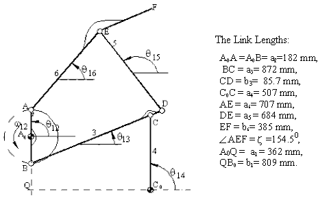
In this problem, for the position analysis stepwise solution and for the velocity and acceleration analysis matrix inversion method will be used.
Define the fixed link lengths:
![]()
![]() w12:=4
w12:=4 ![]()
![]()
![]()
![]()
![]()
![]()
![]()
![]()
![]()
![]()
![]()
Generate the input crank angle for every 50.
![]()
![]()
![]()
![]()
xBk,yBk are the rectangular coordinates of B with respect to C0 with +ve x axis along QC0.![]()
![]()
Convert rectangular coordinates.
to polar coordinates.
 Cosine theorem. for angle BC0C.

Cosine theorem for the transmission
angle BCC0
![]()
![]()
![]()
![]()
![]()
![]()
![]()
![]()
Note that f, b and s are used as dummy variables.


![]()
![]()
x numbers with A0 as the origin.
Coordinates of F in complex numbers:
![]()
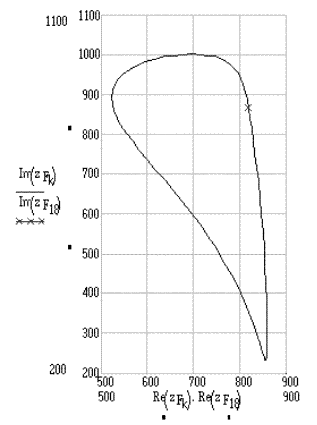
In figure below, The path of point F is shown ( the x sign is the position of point F when q12=900).
|
Path of point F. |
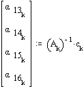
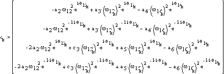
For velocity and acceleration analysis create the coefficient matrix:
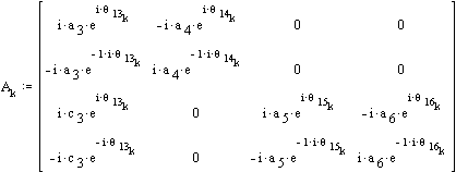
The angular velocities are found from the velocity loop equations.
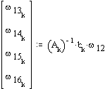
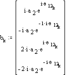
The angular acceleration of the links are found from the acceleration loop equations.
Velocity and acceleration of point F:
![]()
![]()
The polar plots of the velocity and acceleration vectors of point F for a complete cycle are shown below.
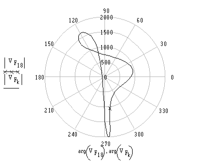
Velocity of point F
(Velocity of F at an instant is the vector from point 0 to a point on the curve e.g
velocity of Point F when q12=900 is the line drawn from 0 to the mark x)
The polar plots of the velocity and acceleration vectors of point F for a complete cycle are shown below.
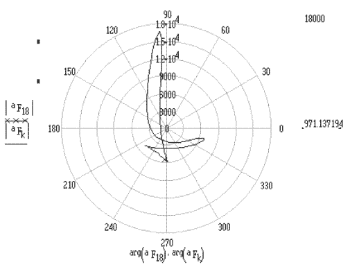
Acceleration of point F
(Acceleration of F at an instant is the vector from point 0 to a point on the curve e.g
acceleration of Point F when q12=900 is the line drawn from 0 to the mark x)
Polar plot of the velocity and acceleration of point F. (velocity and acceleration are measured in mm/s and mm/s2, respectively. The x sign (for k=18) is when q12=900).
In case of graphical solution for the position given, link 2 is in a fixed axis of rotation with w12=4 rad/s. Therefore VA=VB=728 mm/s and while VAis to the left, VB is to the right. Using a scale factor kv=0.5 mm/mm/s we draw these known vectors (Fig. 4.85). Considering the loop formed by links 1,2,3 and 4 The velocity equation is:
VC=VB+VC/B
VC/B is perpendicular to CB and VC is perpendicular to CC0. At the given position, since BA0 and CC0 are parallel, VC and VB must be equal and VC/B =0 and w13=0. In such a case VD=VC=VB. Next consider point E which is a permanently coincident point on links 5 and 6. For points D and E on link 5:
VE=VD+VE/D
Similarly, for points A and E on link 6:
VE=VA+VE/A
VD and VA are of known magnitude and direction. The relative velocities VE/D and VE/A must be perpendicular to ED and EA respectively. Although these two equations cannot be solved separately, when they are equated to each other, the two relative velocity magnitudes are the unknowns. Therefore simultaneous solution is made. For the velocity of point F, we can apply Mehmke's theorem or solve the two vector equations:
VF=VE+VF/E
VF=VA+VF/A ,
simultaneously. ,
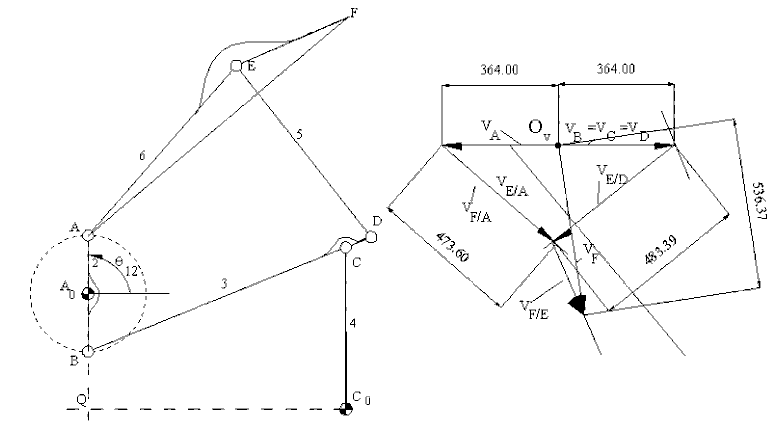
Velocity Polygon
For the acceleration analysis we use the same points that have been used for the velocity analysis. However we have to write the acceleration of these points in terms of their components. Since link 2 is rotating at a constant speed, the tangential accelerations of points A and B are zero (aA=anA , aB=anB). aA= aB =2912mm/s2, both towards the center of rotation. Using a scale factor ka=0.2mm/mm/s2, we draw these vector (Fig.4.80). Next we write the acceleration of point C as:
anC + atC = anB + anC/B + atC/B
anC is a vector along CC0 towards C0 and is of magnitude w213 |CC0|=V2C/|CC0|= 1045mm/s2. anC/B=0 since w13=0 for this position. atC and atC/B are perpendicular to CC0 and CB respectively (unknown magnitudes). Note that while w13=0, a13≠0 .atD/B can now be determined since a13=atC/B /|CB| (anD/B =0). Hence aD is known. For point E we can write:
aE = aD + anE/D + atE/D
and
aE = aA + anE/A + atE/A
anE/D= w215|ED| =V2E/D/|ED| =1366mm/s2, along ED, towards D:
anE/A= w216|EA| = V2E/A/|EA| = 1269 mm/s2, along EA towards A.
Tangential acceleration components atE/D and atE/A are perpendicular to the lines ED and EA respectively (unknown magnitudes). The two equations can now be solved simultaneously to determine the velocity of point E. For the acceleration of point F Mehmke's theorem is applied (triangle aef on the acceleration polygon is similar to the triangle AEF of link 6). The result is shown in Fig.4.86. Hence aF = 1075.5/0.2 =5378 mm/s2 , downwards as shown.
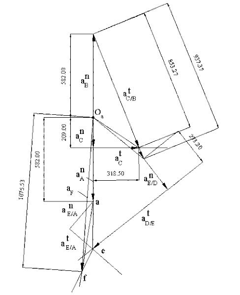
Acceleration Polygon
