3.7 Position Analysis of Mechanisms By Means of Complex Numbers
We have seen that complex number utilisation is a simple and powerful technique for expressing the loop closure equations. The analytical or numerical solution of planar mechanisms can be easily performed by simple algebraic manipulations in complex numbers.
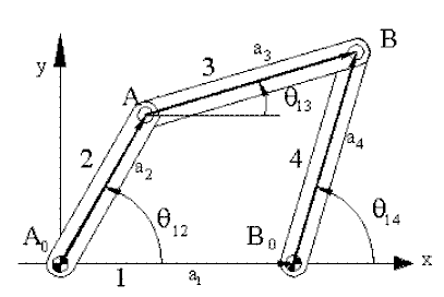
Considering the four-bar mechanism shown below, the loop closure equation in vectorial form is:
A0A + AB = A0B0 + B0B
or in complex numbers:
![]() (1)
(1)

Figure 2.33.
If we equate the real and imaginary parts of this equation separately, we obtain two scalar equations in three position variables (q 12, q 13and q 14). If one of the position variables is the input variable whose value is given, then we shall be able to solve for the values of the other two variables.
In complex plane, when we have an equation in complex numbers, the complex conjugate of the equation is also true (see appendix I). The complex conjugate yields vectors which are the mirror image of the original vectors with respect to the real axis (x-axis); e.g. in case of a mechanism, if we place a mirror about the real axis, as we move the original mechanism its image will also move and corresponding to the original closed loop, the loop formed on the mirror image will also be closed at every position. Hence we obtain another loop closure equation in terms of complex numbers as:
![]() (2)
(2)
The original equation (1) and its complex conjugate (2) are the two independent equations in the complex plane (if we equate the real and imaginary parts of these equations they will yield the same two scalar equations in the real plane).
In general, the loop closure equations yield a non-linear relation between the position variables. The closed form solution of these equations is not straight forward. For simple mechanisms, utilising complex algebra one can solve for the unknown position variables. An iterative numerical solution of these equations will be explained in section 2.5. In this section, closed form solution of the loop closure equations for simple mechanisms will be explained only.
Using the equations (1) and (2), if we are to find q 14 as a function of q 12 , we have to eliminate q 13 from the above equations. We can write the loop closure equations in the form:
![]() (3)
(3)
![]() (4)
(4)
Multiplying equations (3) and (4):
![]() (5)
(5)
![]() Noting
Noting ![]() (6)
(6)
Since ![]() , equation (6) reduces to the form:
, equation (6) reduces to the form:
![]()
or, dividing every term by 2a2a4:
![]()
or:
![]() (7)
(7)
where
![]() ,
, ![]() ,
, ![]()
Equation (7) is called "Freudenstein's Equation" which can be used for the synthesis of four-bar mechanisms. It gives an implicit relation between the position variables q 14 and q 12. In order to obtain an explicit expression for q 14, Freudenstein's equation can be written in the form:
![]() (8)
(8)
Substituting the trigonometric identities:


(This is commonly known as half-tangent form of representation of the sine and cosine function).
Freudenstein's equation results:
![]() (9)
(9)
where
![]()
![]()
![]()
Equation (9) is a quadratic in terms of
![]() .
.

Therefore:
 (10)
(10)
Where the plus or minus sign refers to two different configurations of the four-bar mechanism. Also note that the coefficients of the quadratic (A, B and C) are functions of the link lengths and the input crank angle only. Therefore, if the input crank angle is given, q 14 can be obtained from equation (10) directly.
One can perform a similar procedure to determine the coupler-link angle, q 13, in terms of the input angle, q 12. This is left as an exercise.
Another form of solving equation (8) is to rewrite it in the form:
![]() (11)
(11)
If we let:
![]() (12)
(12)
where
 (13)
(13)
Equation (11) reduces to:
D cosfcosq14 -D sinf sinq14=K2 cosq12 -K3
Then using the trigonometric identity: ![]() :
:
![]() (14)
(14)
or:
![]() (15)
(15)
When solving for f in equation (13), one must remember that for a correct quadrant of the angle either the sign of the x and y components must be checked or double argument inverse tangent function must be used. In equation (15) the two different solutions for the inverse cosine function (= ±f) will yield open or crossed configuration of the four-bar mechanism.

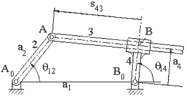
Figure 2.34.
As another example for the solution of loop closure equations in complex numbers consider an inverted slider-crank mechanism where q 12 is the input variable and q 14 is the output variable. We would like to determine q 14 as a function of q 12.
Vector loop closure equation is:
A0A = A0B0 + B0B + BA
and in complex numbers:
![]()
or:
![]() (1)
(1)
and its complex conjugate is:
![]() (2)
(2)
We would like to eliminate s43 from the equations. Therefore:
![]() (3)
(3)
![]() (4)
(4)
Taking the ratio of the two sides and cross-multiplying:
![]()
or
![]() (5)
(5)
noting ![]() :
:
![]() (6)
(6)
Using half-tangent form for cosq 14 and sinq 14 equation (6) reduces to a quadratic equation in  as
as
:
![]() (7)
(7)
where
![]()
![]()
![]()
The solution for Equation (7) can be obtained as in the four-bar example.
If we are to determine s34 as a function of q12, the loop closure equation and its complex conjugate can be written in the form:
![]()
![]()
Multiplying the two equations yields:
![]()