6.2.3. Systems with Resisting Force
In the previous section we have only considered the physical forces and the reaction forces at the joints. Now, let us consider the resisting forces. Since the rigidity assumption is still valid, the resisting forces in mechanisms are assumed to exist at the joint only. Their direction is governed by the direction of the relative motion between the links joined (resisting forces will always oppose the motion). Therefore, for force analysis with resisting forces, the direction of motion of all the links in a mechanism must be known.
There are different types of resisting forces in machinery. One cannot account for these resisting forces exactly. The following three different types of resisting forces are usually assumed to exist.
1. Static Frictional Force is the force that is necessary to slide one body relative to the other. This force is along the contact surface and it is related by the normal force (F32) acting at the contacting surfaces by the equation:
R32= - mF32
The proportionality constant m is known as the coefficient of static friction. The negative sign is used simply to denote that R32 tends to oppose the motion. Note that the static frictional force exists before the motion has actually started. If there is no force component acting parallel to the surfaces, the resisting force will not exist. If the magnitude of the force component parallel to the contacting surfaces (say, Ft), is less then R32, the magnitude of the resisting force will be that which brings the system into equilibrium (R32=Ft ), but the magnitude will never be greater then mF32
. 2. Sliding Frictional Force is the force necessary to keep the relative motion of two sliding bodies continuously. It is also given by the equation R32= - mF32, but, in this case, m is the coefficient of sliding friction, which is less than the coefficient of static friction. Sliding friction is also known as Coulomb friction.Experiments have shown that the static or sliding friction force does not depend on the area of contact. It depends on the types of materials in contact, on the surface quality in contact and the type of film formed between the contacting surfaces. The coefficient of static friction is slightly larger then the coefficient of sliding friction.
3. Viscous Damping Force is proportional to the relative velocity of the two contacting surfaces and is given by:
R32 = -cv2/3
Where c is the coefficient of viscous friction and v2/3 is the relative linear velocity. Viscous friction assumes that there is a fluid film between the two surfaces in contact.
The resisting force is usually a combination of viscous and sliding friction forces. If a joint is well lubricated and if the relative velocity between the two kinematic elements is almost a constant, viscous damping force will be dominant (e.g. in continuously rotating gear boxes or in shaft bearings. In cases of poor lubrication or in cases where the relative velocity changes its magnitude and direction considerably, sliding frictional force assumption will be more valid since the lubrication film between the two contacting surfaces cannot be kept at all times. This is the case in mechanisms. The value of the sliding and static friction coefficients must be obtained by experiments and the values obtained will be approximate (It may change in time). In force analysis of mechanisms Coulomb friction is usually assumed. Since the values are approximate, sliding and static coefficients of friction are taken as equal. For lubricated steel surfaces sliding friction coefficient lies between 0.02 and 0.2 depending on the surface finish and the type of lubrication. In certain applications coefficient of friction may be increased by using abrasive material at the joints.
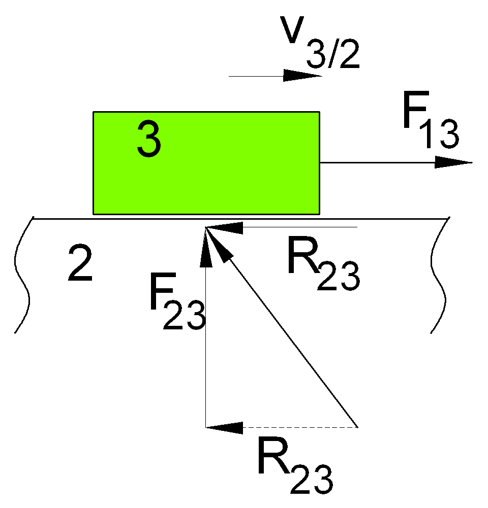
In prismatic joints, the reaction force between the two links in contact will not be perpendicular to the slider axis if resisting force is taken into account. The resultant reaction force will be inclined as shown. The angle f which is known as the friction angle is:
tanf = m =![]()

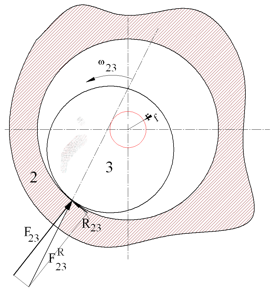
In revolute joints without the resisting force, the line of action of the reaction force F23 will pass through the centre of the joint. Due to the resistance to the relative motion, there will be sliding frictional force R23:
R23= - mF23

R23 is in the opposite direction of the relative motion as shown. The sum of the resisting and the reaction force will give the total reaction force F23R:
F23R= R23+ F23
The line of action of F23R will not pass through the centre of the joint but will be tangent to a circle, which is known as the friction circle. The radius, rf , of this circle is equal to:
rf=rsinf
r is the radius of the revolute joint. For small angles sinf=tanf:
![]()
note that the friction circle is independent of the magnitude or the direction of the transmitted force.
The reaction force tangent to the friction circle can be replaced by a force passing through the centre of the joint and a moment (friction torque) which is in opposite direction of the relative motion and which has the magnitude:
M32=rf F23R
M32 will always be directed opposite to the relative angular velocity direction. In analytical methods the frictional torque plus the reaction force acting at the centre of the joint will be more useful. In graphical methods force tangent to the friction circle is used.
Neither the equivalent mechanism concept nor the principle of superposition can be used in cases when there is resisting force. This will usually complicate the solution of a problem. However, in mechanisms since the radii of the revolute joints are quite small in comparison to the link lengths and since the coefficient of sliding friction is usually less than 0.2 , the friction circles are of negligible diameter when you compare it with the link lengths. Hence, one can easily neglect friction in such cases. When the mechanism is at or near a critical position or when the revolute joint is of considerable size, as in the case of eccentrics, its effect cannot be neglected.
5.2.3.1 Static Force Analysis with Friction
In case of systems with resisting forces usually there is no simplification in the equilibrium equations, eg. three equilibrium equations for each link must be written. in geometrical methods the friction circle or the friction angle at the joints will be quite useful. When an analytical solution is required one must use the resisting force or the resisting moment created at the joints directly. The equations to be solved become nonlinear when there is external force on two or more links. The procedure will be explained by two examples.
Please remember that for a solution, a correct free-body diagram is essential. Using this free-body diagram one can easily determine the necessary mathematical approach for the solution. The known values and unknown values in the problem can easily be identified.
In performing the static and dynamic force analysis of machinery, almost always the free-body diagram of each rigid body is drawn and the known forces are identified. One has to solve for the remaining unknown.
|
|