4.2 VELOCITY AND ACCELERATION ANALYSIS OF MECHANISMS-2

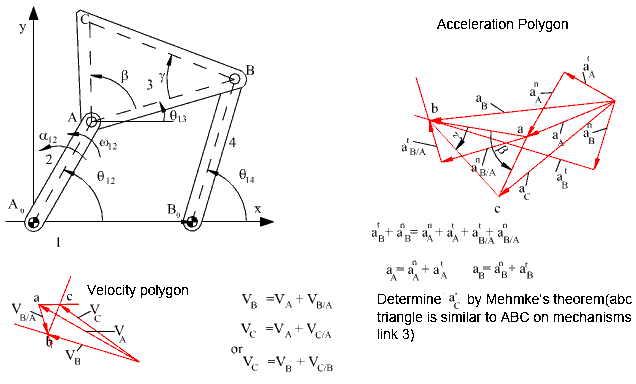
As for the velocity and acceleration analysis of a four-bar mechanism, a similar approach can be used. The loop closure equation and its complex conjugate is:
![]()
![]()
The first derivative of the loop closure equation (velocity loop equation) is:
![]()
![]()
Note that the velocity loop equation in vector form is:
VA+ VB/A = VB
In complex numbers, the magnitude and direction of each velocity term can easily be identified. The velocity loop equation is a simple way of writing the velocity vector polygon. The velocity loop equation and its complex conjugate can be used to solve for the velocity variables w13 and w14for a given input velocity w12, provided that the position variables q13and q14 are solved for a given input angle q12:

or:
![]()
similarly:

![]()
If the velocity of the coupler point C is to be determined:
![]()
The derivative of the position vector will give us the velocity vector:
![]()
Which is the vector velocity equation:
VC=VA VC/A
In terms of Cartesian components:
![]()
![]()
If the position and the velocity loop equations are solved, one can easily determine the terms on the right hand side of the equations. Once the x and y components of the velocity is determined one can as well transform the velocity vector into polar form to yield the magnitude and direction by writing the velocity vector in the form:
VC = VCeih
Where ![]() = magnitude of velocity, and
= magnitude of velocity, and  .= the angle the velocity vector makes with
respect to positive x axis.
For the acceleration analysis, the second derivative of the loop closure equation (acceleration loop equation) is:
![]()

Note that the acceleration loop equation is nothing but the acceleration vector equation in the form:
![]()
Rearranging the terms so that only the unknown acceleration variables are on the left hand side of the equation:
![]()

Solving the two linear equations for the acceleration variables:

and

The acceleration of the coupler point C can be obtained from the second derivative of the position vector:
![]()
Hence, after the solution of the position, velocity and acceleration loop equations, one can easily determine the position, velocity and acceleration of any point in any one of the links of the mechanism. The graphical solution of the velocity and acceleration vector equations are as shown in below.

The velocity and acceleration loop equations are always linear in terms of the velocity and acceleration variables. It is the solution of the loop equations that require more effort since they are nonlinear The above procedure can be explained step by step as follows.
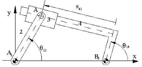
Consider the inverted slider-crank mechanism shown below. The loop closure equation was:
![]()
The velocity loop equation will be obtained by differentiating:
![]()
or, regrouping terms:
![]()

This velocity loop equation is the velocity vector equation:
![]()
The first term is the velocity of point A2 on link 2, whose magnitude is equal to the distance from the centre of rotation (A0A=a2) times the angular velocity of link 2 (w12). Since points A2 and A3are permanently coincident points, their velocities are equal. The second term is the velocity of point A4 on link 4 whose magnitude is equal to the distance from the centre of rotation (B0B=a4) times the angular velocity of link 4 (w14). The third term is the relative velocity of point A3 with respect to link 4 whose direction is along the slider axis between links 3 and 4.
The acceleration loop equation is:

Which is the acceleration vector equation:
![]()
The tangential and normal components of points A2 and A3 are equal. The normal and tangential components of A4 are along B0A and perpendicular to B0A respectively. The third term on the right hand side is the relative tangential acceleration which has the magnitude ![]() and along the slider axis. The last term is the Coriolis acceleration component with magnitude
and along the slider axis. The last term is the Coriolis acceleration component with magnitude ![]() perpendicular to the slider axis.
perpendicular to the slider axis.
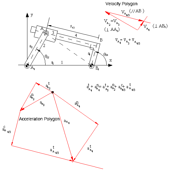
.Graphical velocity and acceleration analysis of the mechanism is shown for the position given below. Note that the velocity vector equation used is:
VA4=VA3+VA4/3

Since VA3=VA2, The magnitude of this vector is w12|AA0|. VA4 is perpendicular to AB0, VA4/3 is a vector parallel to the slider axis. First VA3 is drawn using a certain scale. Then a line parallel to the slider axis is drawn from the tip of VA3 and a line perpendicular to AB0 is drawn from the starting point of VA3. The intersection of these to lines gives the solution, the magnitude and the direction of VA4 and VA4/3 can be determined. When VA4 is determined, w13 can be determined by dividing VA4 with AB0 distance. From the velocity polygon we also note that w13 must be counter clockwise for point A4 to have the shown velocity direction.
For the acceleration analysis, the acceleration vector equation is rewritten as:
atA4+anA4= atA3+anA3+acA4/3+ atA4/3
so that there is one unknown on each side of the equation. We start with the known vector atA3=atA2 (its magnitude is a12|AA0|, and its direction is perpendicular to AA0 in the sense of a12), and anA3=anA2 (its magnitude is w212|AA0|, and its direction is along AA0, always directed to the centre of rotation, A0). We draw these vectors using a certain scale ka, Then we determine the magnitude and direction of Coriolis acceleration, acA4/3. Its magnitude is 2w13VA4/3 (the angular velocity that changes the direction of the relative velocity must be used). The direction of coriolis acceleration is determined by rotating the relative velocity vector VA4/3 900 in the sense of w13. After drawing acA4/3, we draw a line tangent to the slider axis which is the direction of atA4/3. Next, we consider the left hand side of the equation. We draw the normal acceleration anA4 since its of magnitude
w213|AB0| (or = ![]() ), and its direction is along AB0 towards B0. Then we draw a line normal to the line AB0, which is the direction of atA4 (of unknown magnitude).The point of intersection of the two lines is the solution of the acceleration polygon.This procedure is explained in step as follows:
), and its direction is along AB0 towards B0. Then we draw a line normal to the line AB0, which is the direction of atA4 (of unknown magnitude).The point of intersection of the two lines is the solution of the acceleration polygon.This procedure is explained in step as follows:
In the following examples the displacement, velocity and acceleration analysis of some mechanisms will be shown with numerical values using graphical or analytical methods.