6.2. STATIC FORCE ANALYSIS OF MACHINERY
6.2.1 Systems without Resisting Force
Initially, we shall neglect the forces associated with the inertia of the links and the resisting forces. Later, we shall include the resistive forces and consider the inertia effects.
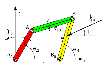
Static force analysis makes direct use of static force equilibrium equations. For an analytical solution formulation one must draw the free-body diagram of each rigid body and must identify the unknown forces. Next, one must write the static force equilibrium equations for each link. If a correct formulation is performed, the resulting equations will be equal to the number of unknown force components and these equations will be linear in terms of the unknowns. Let us illustrate this by a simple four-bar example shown below:

The system is in equilibrium under the action of the external force F14 and T12. The magnitude and direction (h) of the force F14 are known. We are to determine T12 and the forces acting at the joints. In free-body diagrams of the moving links are shown.
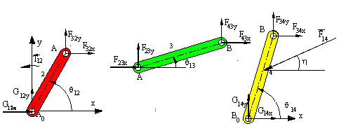
On the free-body diagrams the unknown joint force components (Fijx and Fijy) are all shown acting in the positive x and y directions. a negative value is obtained in the result, it means that force component is in the opposite direction. In the example shown the equilibrium equations and the equalities due to Newton's third law (Fijx = -Fjix ) result with 13 scalar equations in 13 unknowns (T12,F32x, F32y, F23x, F23y, F43x, F43y, F34x, F34y, G12x, G12y , G14x, G14y).
For link 2:
| F32y + G12y = 0 | (SFy= 0) | (1) |
| F32x + G12y = 0 | (SFx= 0) | (2) |
| F32ya2cos(q12) - F32xa2sin(q12) + T12= 0 | (SMA0= 0) | (3) |
For link 3:
| F23x + F43x = 0 | (SFx= 0) | (4) |
| F23y + F43y = 0 | (SFy= 0) | (5) |
| F43xa3sin(q13) + F34ya2cos(q13)= 0 | (SMA= 0) | (6) |
For link 4:
| F34x + G14x-F14cos(h)= 0 | (SFx= 0) | 7) |
| F34y + G14y-F14sin(h) = 0 | (SFy= 0) | (8) |
| F34xa4sin(q14) + F34ya4cos(q14)+ F14r4(cos(h)sin(q14)-sin(h)cos(q14)) 0 | (SMB0= 0) | (9) |
and due to action-reaction (Newton’s third law):
| F32y = - F23y | (10) |
| F32x =- F23x | (11) |
| F43y = - F34y | (12) |
| F43x = - F34x | (13) |
If the displacement analysis is performed beforehand, e.g. if q13, q14 values are determined for different q12 values, the above equations can be used for every position of the mechanism. Another important point is that this formulation is very general. It can be used for mechanisms where there are several external forces acting on the same or different links and in cases where we have resisting forces at the joints. However, the resulting number of equations is usually too large (if there are l links in the mechanism there will be 3(l-1) equilibrium equations).
One can reduce the number of equations to be solved if the free-body diagrams are analysed to some detail. One need not write the forces in terms of its x and y components if the direction is known and one can identify the forces that are of equal magnitude before attempting for a solution. The free-body diagrams of the links in the four-bar mechanism are redrawn below.
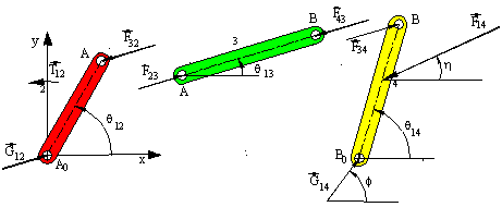
F13 = - G12
Hence:
F 43= -F32 =-F34= -G12= -F23
Now, one can solve for the unknown forces if we write the 3 equilibrium equations for link 4 and one moment equilibrium equation for link 2, which are
- F14 cosh + F34cosq13+ G14 cosf = 0 or F14 cosh + F34cosq13+ G14x= 0
- F14 sinh + F34sinq13+ G14 sinf = 0 or F14 cosh + F34cosq13+ G14y= 0
r4F14(cosh sinq14 - sinh cosq14)+a4F34(sinq13 cosq14- cosq13sinq14) = 0
And
a2F32(cosq13sinq13-sinq13 cosq12) + T12 = 0 (F32 = - F34)
There are four equations with four unknowns (F34, T12, G14,f or F34, T12, G14x, G14y). If the magnitudes come out negative, the direction of the force or torque is opposite to that indicated on the free-body diagram. If we generalise the above result, we can see that:
a) For two-force members you don't have to write the equilibrium equations. You can simply state that the forces are equal and opposite and their line of action coincides with the line joining the points of applications.
b) For two-force plus a moment members you must write the moment equilibrium equation only. The two forces are equal and opposite and they form a couple equal and opposite to the moment applied.
c) In case of three or four force members, the three equilibrium equations (SFx = 0, SFy = 0, SM= 0) must be written.
Another simplification in the solution of moment equilibrium equations will result if we use unit vector in the direction of the forces and write a force vector in the form
F = Fv
Where F is the magnitude of F and v is a unit vector in the direction of the force F.
We can similarly show the position vector r as :
r = ru
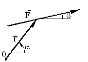
Where r is the distance from point C to a point on the line of action of F and u is a unit vector in the direction of r. The moment of the force F about an axis passing through 0 and perpendicular to the plane will be:
M = rxF = ruxFv = rF(uxv)
Since
u = 1 <a = cos a i + sin a j ;
v = 1 < b = cos b i + sinb j
u x v = (sin b cos a - cos b sin a ) k
Or:
u x v = sin (b- a ) k
Hence M = rxF = r F sin (b - a ) k
Now, the free-body diagrams of the previous example are redrawn
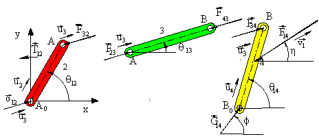
The moment equilibrium equations are:
a4u4 x F34u3 + r4u4 x (-F14)v1 (SMB0 = 0 )
a2 u2 x (-F32 )u3 + T12 k = 0 (SMA0 = 0 )Which result in:
a4 F34 sin(q13 -q14 ) - r4 F14 sin( h-q14 ) = 0
-a2 F32 sin(q13 -q12 ) + T12 =0
One can see that the above equations are exactly the same equations that we have obtained previously.
If we were to solve the equilibrium equations graphically, note that link 4 is a three-force member and the forces must be concurrent. Since the line of action of the force F34 and both the magnitude and direction of F14 are known, the point of concurrency is at the intersection of the lines of action of these two forces Hence the line of action of G14 is the line joining B0 with the point of concurrency. Next, one can draw the force polygon:
F14 +G14 +F34 =0
We want to determine the magnitudes of the forces G14 and F34 . To do this, the force F14 is drawn as a line vector whose length is proportional to the magnitude of the force by utilising a certain force scale (kf mm/N). Since F43 =-F34 (Newton’s third law), F23 = -F43 (equilibrium of a two force member), F32 = -F23 (Newton’s third law) and G12 =-F32 (equilibrium of a two-force and a moment member), all the joint forces has been determined. To determine the torque T12 , one can measure the perpendicular distance, h, from point A0 to the line of action of F32 and T12 =hxF32 . The direction of the input torque must be opposing the moment of the couple created by F23 and G12 . The resulting free body diagrams and the force polygon is as shown:
As another example, consider the slider-crank mechanism shown
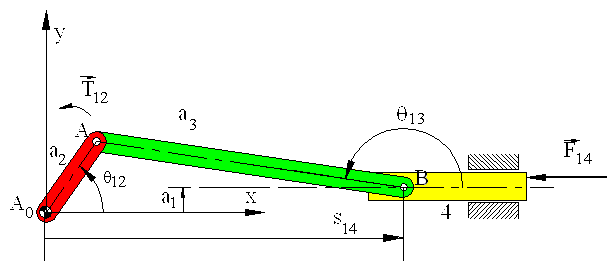
. The system is in static equilibrium for all crank angles under the action of a known force F14 acting on link 4 and unknown torque T12 acting on link 2. We are to determine the joint forces and the input torque, T12 .
Note that link 3 is a two force, link 2 is a two force and a moment member. In case of link 4, there is a known external force F14 , a joint force F34 whose direction is known (along AB). There must be a joint force G14 (perpendicular to the slider axis) and moment M14 (perpendicular to the plane) due to the action of link 1 on link 4 . The rigid body is in equilibrium under the action of three forces and a moment.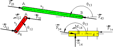
The force G14 can be placed anywhere on link 4. Since link 4 is in static equilibrium, this will change the magnitude of the moment M14 . If the line of action of G14 passes through the point of intersection of F14 and F34 , the moment M14 will be zero and rigid body will be in equilibrium under the action of three forces.If the point of concurrency, O, of the three forces lie within the physical boundaries of the sliding joint, there will be surface contact between links 1 and 4. (In the figure the contact is at the bottom surface, If the direction of G14 is downwards instead of upwards, contact will be at the top surface) and link 4 will not be subjected to a rotary motion within the slide. However, if the point of concurrency, O, lies outside the boundaries (b), the force G14 is a fictitious force which is the resultant of the forces acting at the contact region (Due to equilibrium under the action of the three forces: G14 +F34 +F14 =0).

(a) Point of Concurrency is within the Joint Boundary (b) Point of Concurrency Outside Joint Boundary
Physically, the joint forces must occur due to action and reaction between two contacting surfaces on two different links. In cases as shown in figure (b), since the forces acting on link 4 tends to rotate link 4, if we assume complete rigidity of the links, links 1 and 4 will be in point contact at the two edges of the boundaries as shown At the contact points There will be joint forces G’14 and G”14 whose directions are perpendicular to the slider axis (actually these forces will be perpendicular to the common tangent between the two contacting surfaces. In normal machine systems since the clearance at the joint is small compared to the dimensions of the joint, the angular rotation is negligible and this assumption is valid).
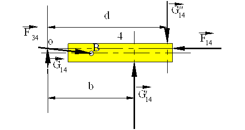
Also note that:
G14 = G’14 + G”14 (In terms of magnitudes, G14 = G’14 - G”14 for the case shown)
G "14d=G'14b
G14 can be of a very small magnitude while the actual contact forces G’14 and G”14 can be of considerable magnitudes.
If one is only concerned with the force equilibrium, any one of the equilibrium diagrams for link 4 would be correct and valid. However, if one is interested with the actual joint forces, the type of contact and the actual magnitudes of the forces at the point(s) of contact must be determined. This will also have an important role when friction in these joints must be taken into account. The magnitudes of G’14 and G”14 will depend on the on the geometry of the joint as well as the magnitude and the direction of the other forces acting on the link. Also note that within one cycle of the mechanism the type contact between links 1 and 4 will change. There will be four different modes of contact as shown (G14= - G41). Note that the magnitudes of all the forces and the dimensions must all be positive for all the four modes. Otherwise the mechanism is not in the assumed mode of contact.
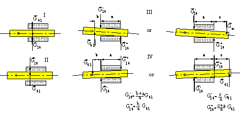
Modes of Contact for a Prismatic Joınt
Example 6.1.
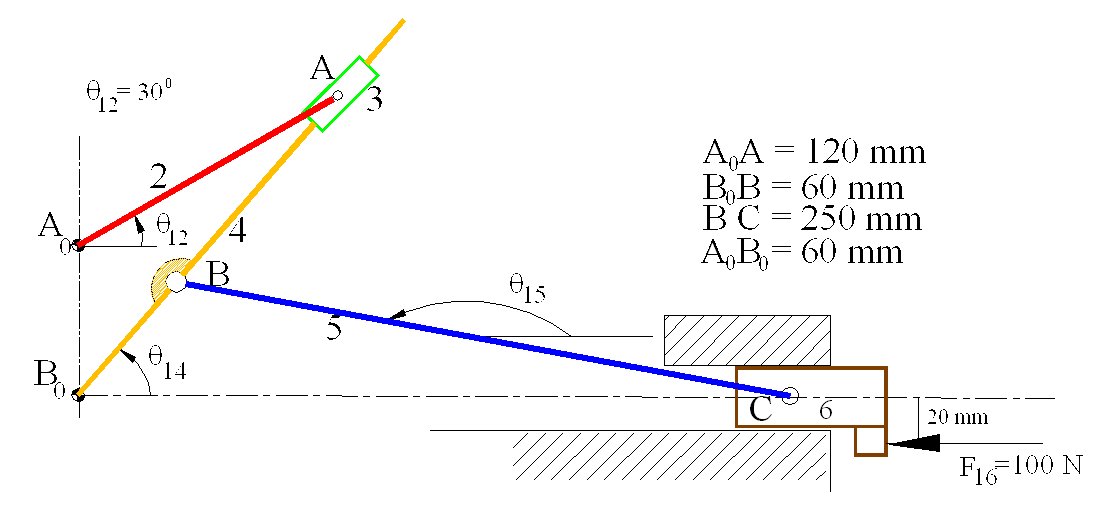
B0A = 158.75 mm; q14= 49.110 B0C = 285.13 mm; q15 = 169.550
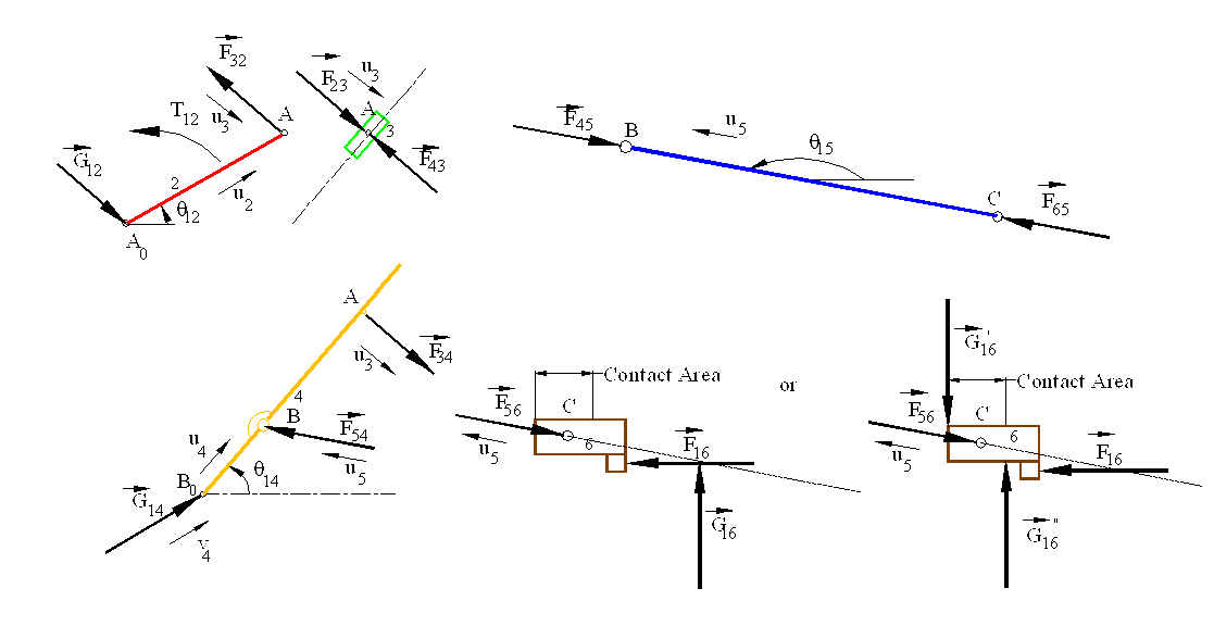
The free-body diagram of each link is shown above.. We note that links 3 and 5 are two-force and link 2 is a two-force plus a moment member. For link 6 if we assume that there is a single joint force between links 1 and 6, we note that the point of concurrency and the resultant joint force, G16 is outside the boundaries of the points of contact and that it is of mode is III .
We have:
F56 = - F65 = F45 = -F54
F34 = - F43 = F23 = -F32 = G12
F56 = - F56 u5 where u5= 1 < 169.950 = cos(169.950)i +sin(169.950)jF16 = -100 i (N)
G”16 = G”16j and G’16 = -G’16j
Force equilibrium of link 6 results:
(G”16- G’16)j - F56 u5 - 100 j = 0
or
(G”16- G’16)- F56 sin(169.950) = 0
- F56 cos(169.950) -100 = 0
The moment equilibrium equation (SMC= 0) yields (the distance from point B to the two boundaries are 70 and 30 mm respectively. These distances will be a function of the mechanism position):
G’16*70 +G”16*30 -100*20=0
We obtain:
F56 = 101.56 N <-10.050; G’16= 14.68 N < 900; G”16= 32.41 N < 900
Since link 5 is a two force member F54=-F45=F65=-F56=107.56 N < 169.950.
The force equilibrium equation for link 4 is:
F54u5 + G14v4 + F34u3 = 0
Where
v4 = 1 < f= cosf i + sinf j
u3 = 1 <(q14 -900) = cos 40.890 i - sin 40.890 j
The force equilibrium equations can also be written as:
F54 cos 169.950 + G14 cosf + F34 cos 40.890 = 0
F54 sin l69.950 + G14 sin f-F34 sin 40.890 = 0
The moment equilibrium equation (SMB = 0) is:
a4u4x F54 u5 + r4u4x F34 u3 = 0
Where:
u4 = 1 < q14 = cos 49.110 i + sin49.110 j
and
B0B = a4 = 60 mm , B0A = r4 = 158.75 mm
When the moment equilibrium equation is simplified:
a4 F54 sin(q15-q14 + r4 F34 sin(q14-900 -q14) =0
or:
a4 F54 sin(120.440) - r4 F34 = 0
For link 2 :
F32 = 33.14 N < 139.110
G12 = 33.14 N <40.890
And the moment equilibrium equation yields:
T12 + 120 * 33.14 sin(139.110 -300 ) = 0
or
T12 = -3757.65 N-mm
or
T12 = 3.76 N-m (CW)
Example 6.2.
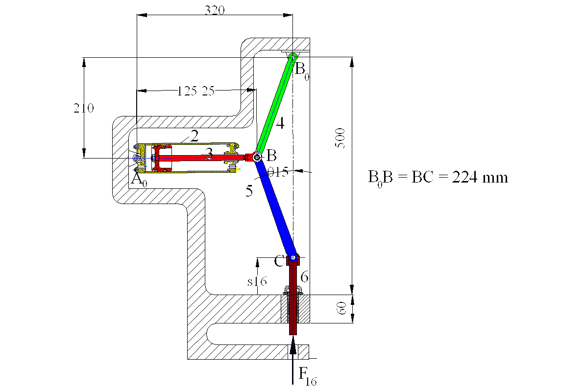
Consider the pneumatic press shown. It is a six link mechanism. The force F16 applied by the work piece onto the ram (link 6) is brought to equilibrium by the pneumatic pressure applied to the piston and cylinder.
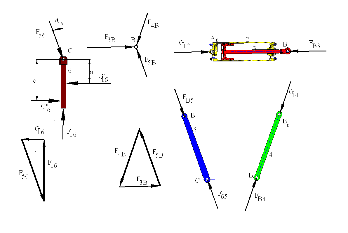
Consider the free-body diagrams of the moving links. When link 6 is considered as a three-force member, the point of concurrency is point C, which lies outside the sliding joint boundaries. G16 is a fictitious force, which is the resultant of G'16 and G"16. We can write :
F56+F16+G16=0
G'16-G"16 =G16
aG'16=cG"16
When F16 and the position of the mechanism is known, the above equations can be used to determine G'16, G"16and F16
When we consider link 5, since there is a ternary joint at B between links 4,5 and 3, we must know how this joint is constructed.

As shown above, either the pin can be a rigid part of one of the links (say link 3) and the other links (4 and 5) are connected to this link (in this case there is no joint between links 4 and 5), or the pin is a separate free body to which all the three links are connected. It is a common practice to consider the free-body diagram of the pin when there is a joint of degree greater than one. The pin B will be under the action of the three concurrent forces F3B, F4B, F5B (F3B+F4B+F5B=0) . Now, when we consider links 4 and 5, these links are in equilibrium under the action of two forces. (for link 5: F65=-F56= -FB5= F5B, and for link 4: F4B=-FB4= -G14).
(a) (b)
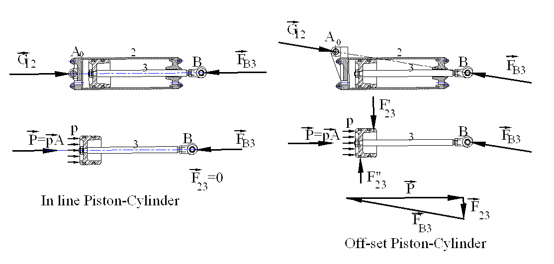
When we have the piston cylinder arrangement, instead of considering the free body diagrams of the piston and the cylinder separately, it is more convenient to draw the free-body diagram of the two links (piston and cylinder) together, as shown in (a). The hydraulic pressure is an internal force which is in equilibrium and the only external force acting on the system are the two joint forces G12 and FB3 (= -F3B), which must be equal and opposite (G12= F3B)and their line of action is along the line joining the points of application (A0B). Now the force equilibrium equation F3B+F4B+F5B=0 can be solved since the direction of the forces F3B, F4B and the magnitude and direction of F5B (=F65=-F56) are known. If the slider axis between links 2 and 3 is coincident with the line A0B, then there will be no joint force at the sliding joint (i.e. F23= -F32=0 and P=-FB3) as shown. If the piston cylinder is eccentric as shown in (b), then from the free-body diagram of the piston-cylinder as a whole the line of action of G12 and FB3 can be determined. When the free-body diagram of the piston is drawn, we note that here is the joint force F'23 and F"23 acting between links 2 and 3. Note that even if F23 is quite small, the magnitudes of the forces may be quite large (this why in all construction machinery and the like we have in line piston-cylinder arrangement. Off-set piston-cylinder is used if there is no choice.)