4.2 VELOCITY AND ACCELERATION ANALYSIS OF MECHANISMS-3
Example:

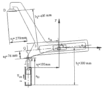
For the mechanism shown., the piston (2) has an upward velocity VA= V12=180 mms-1 (linear velocity of link 2 with respect to link 1). We are to determine the velocity and acceleration of point D. In this example the loop closure, velocity and acceleration equations have been solved explicitly. It is left to the reader to derive the equations used.
Define the fixed lengths:
![]()
![]()
![]()
![]()
![]()
![]()
![]()
Position Analysis
![]()
![]()
![]()
![]()
![]()
![]()
Path of point D (with A0 as the origin and x axis is the horizontal line for the coordinate frame used):
![]()
Velocity analysis
![]()


![]()
Acceleration analysis


![]()
Some numerical results:
When: ![]() ;
; ![]() ;
; ![]() ;
; ![]()
![]()
![]()
![]()
![]()
![]()
![]()
![]()
![]() mm
mm ![]()
![]()
![]()
![]()
![]()
![]()
![]()
![]()
![]()
![]()
Polar Plot of displacement, velocity and acceleration of point D is as shown in Fig. 4.79. The vectors are shown for s2/1=60 mm.

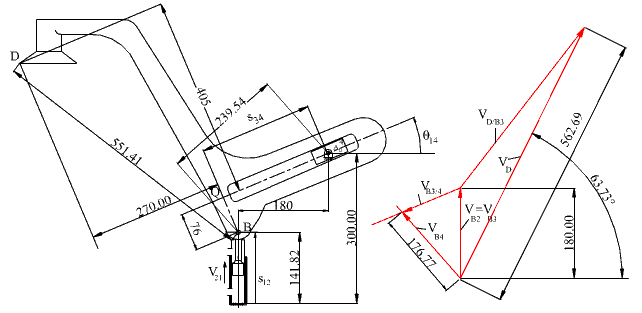
If we perform the velocity analysis graphically, we have to solve the velocity vector equation:
VB4=VB3+VB4/3
The velocity VB3 is equal to VB2=V2/1. The relative velocity VB4/3 must be parallel to the slider axis between links 3 and 4 since these two links can only translate along the slider axis relative to each other. VB4 is perpendicular to the line A0B since link 4 is in a fixed axis of rotation about A0. We first lay out VB2 with a kv=1mm/mms-1 and then draw a line parallel to the slider axis from the tip of VB2. From the starting point we draw a line perpendicular to A0B. The intersection of these two lines gives us the magnitudes of VB4 and VB4/3 (e.g. VB4 = 176.77mm/kv = 176.77mms-1 ) . When this velocity vector equation is solved, we can determine w14= VB4/|A0B| (176.77/239.54=0.738 s-1). The direction of this angular velocity must be clockwise in accordance to VB4. w14= w13 since there is no relative rotation between links 3 and 4. Then we can solve the vector equation:
VD=VB3+VD/B3

Velocity polygon for the example
VD/B3= w13|DB| (=0.738*551.41=406.91mm/s) and the direction of VD/B3 is perpendicular to DB in the sense of w13. The sum of these two vectors gives us VD as shown in Fig. 4.76. The result is in close agreement with the analytical solution.
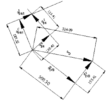
For the acceleration analysis we can write the acceleration vector equation:
atB4+aanB4=aB3+atB4/3+acacB4/3
Considering B4, the tangential acceleration atB4 is of magnitude a14|BA0| (unknown a14) and its direction is perpendicular to BA0. The normal acceleration is of magnitude w214|BA0| =V2B4/|BA0| (= 130.45mm/s2) and its direction is along BA0 towards A0, center of rotation. Since B3 and B2 are permanently coincident, they have the same velocity and acceleration. Assuming that the piston is moving at a constant speed, aB2=aB3=0. The tangential relative acceleration atB4/3 is along the relative path, which is the slider axis between 3 and 4. Its magnitude is an unknown. The Coriolis acceleration acB4/3 is of magnitude 2w14VB4/3 (=187.32 mm/s2). Its direction perpendicular to the slider axis and is determined by rotating the velocity vector VB4/3 900 in the sense of w14. Drawing these acceleration vectors by a certain scale ka (=1mm/mms-2), we determine the magnitudes of atB4 and atB4/3 . Next, for the acceleration of point D:
aD= aB3+ anD/B + atD/B
Since we do not know the path of point D, we cannot separate aD in to its components. aB3=0. The normal relative acceleration anD/B is of magnitude w213|BD| (= 300.32 mm/s2) along BD towards B. Note that w13=w14, since there is no relative rotation between links 3 and 4. The relative tangential acceleration atD/B is of magnitude a13|BD|. Since a13=a14=atB4/|BA0| (= 0.640 s-2) atD/B= 153.41 mm/s2 ,perpendicular to DB in the sense of a13. The sum of these known vectors will give us the acceleration of point D at the instant considered as shown in

Acceleration Polygon for the example