5.1 SIMPLE GEAR TRAINS
A gear train is called a simple gear train, if the axes of the gears are connected by revolute joints to the fixed link. The geometric representation of a gear train with one gear pair is shown below. In the figure the solid model of the gear train (and its simulation) is also shown. The circles drawn as centerline is the known as the pitch circle of the gear. The linear velocity of the point of contact P, is the point where the relative velocity between the two links is zero (there is pure rolling and no sliding between the toothed surfaces). The gear ratio R23 is defined as:
![]()
Where n1j is the angular speed of link j with respect to the fixed link 1 expressed in rpm. Velocity of point P is:
![]()
Hence: ![]()
Simple Gear Train
Geometric Representation of Gears in External Mesh (P in between centers)
Where dj and rj are the diameters and radii of the pitch circles of the gears.
From the law of gearing for the gears to be in mesh, the diametral pitch, which is the ratio of the number of teeth over the pitch diameter must be the same for two mating gears: e.g.:
| Diametral pitch |
Where Tj is the number of teeth on gear j. In European countries rather than the diametral pitch, Module, m , which is the ratio of the pitch circumference to the number of tooth (pdj/Tj), is used. Unit for diametral pitch is in 1/inch and the unit for module is mm.
we define that the gear ratio as positive when the two gears in mesh are rotating in the same direction and negative if they are rotating in the opposite direction. As seen in the figure above, if P is in between the fixed centres, the gear ratio will be negative and such gear pairing we shall call “external mesh”. If the pairing is as shown below., The point of contact is outside the fixed centres and the gear ratio is positive. Such gear pairing will be called “internal mesh”.
Gear train with Internal Mesh (P outside the centers)
Therefore, the gear ratio of a gear train with one gear pair can be expressed as:
![]()
+ if internal,
- if external mesh.
Simple Gear Train with more than one gear pair
Simplest gear trains have one gear pair on each link. A simple example is , shown in Fig. 6.3. The overall gear ratio of the gear train, R24, will be:
![]()

Hence, for such gear trains, the intermediate gears have no effect on the gear ratio, except the sign of the gear ratio. These intermediate gears are usually called idlers. They are used either to change the direction of rotation or they can be used to transmit motion between two shafts that are far apart while the gear sizes are kept small.
A Compound Gear train
A gear train is called a compound gear train if there is more than one gear on each link. An example is shown above. In a compound gear train there may be some idler gears. The gear ratio for the whole gear train can be determined by considering the gear ratio for each gear pair.
We can write:
![]()
![]()
![]()
![]()
Then ![]()
![]()
Note that the gears that appear in the numerator are all driving gears and those that appear in the denominator are all driven gears. Also, each external gear mesh changes the sign of the gear ratio once. If the number of external gear meshes is odd, the gear ratio will be negative; if it is even, the gear ratio is positive. We can generalise the above result and define the gear ratio for any simple compound gear train as:
![]()
where k refers to the number of external gear pairs.
The gear ratio is a constant. Therefore, the angular displacements and the angular accelerations are also related with the same gear ratio (e.g. if link i is rotated by Dq1ithe corresponding angular rotation of link j, Dq1j, is:
Dq1j=RijDq1i.
We can generalise what we have obtained for simple gear trains to other linear mechanical systems. In case of belt drives the pulley diameters must be used instead of the tooth numbers. In roller drives one can use the roller diameters. For chain drives, one can either use the number of teeth on the sprocket or the sprocket diameter. Assuming that there is no slippage, for the friction drives we can write:
![]()
In this case, k will refer to the number of externally meshed rollers or in case of chain and pulley drives, it will refer to the number of crossed chains or belts. An example is given below.
Crossed belt |
|
 |
Another type of simple gear train is the gear train that is used to change the output speed for a constant input speed. Most common examples are the transmission boxes in cars or in machine tools. In general, they are called speed-change gear trains and they are made up of compound gear trains in which the output speed can be changed by meshing different gears in the train. For each speed ratio one can treat the gear train as a different compound gear train and thus obtain the gear ratio for that particular arrangement. Two examples are given below a four speed manual gear box is shown. Five speed gear boxes can also be seen in most cars that use the same principle (to increase the fuel efficiency). Using the gear shift lever one of the gears is engaged to the output shaft with one of three clutches. These clutches permit engagement while the shafts are rotating and are known as “synchromesh clutch". This type of clutch permits some amount of slippage between the two mating parts in the first phase of engagement while the shafts rotate at different speeds and when the two shafts are at the same speed, a positive engagement is realized. In these figures the side view of the gear trains are shown, since in the front view there will be several concentric circles.
 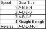 |
4 speed gear box fro a car
One other future of the gear box is that all the mating gears have the same centre distances, or the sum of the radii of two mating gears (A-B, F-C, G-D) since the distance between the output and the intermediate shaft is constant. If the gears are to be made with the same pitch or module, than the sum of the number of teeth of any two mating gears must be the same (in Fig. 6.7: 17+43; 24+36; 33+27 are all equal to 60). Such a gear train arrangement is also known as “reverted gear”.

Double Clutch Gear Box (6 speeds)
In Fig.6.8 a new type of car gear box known as “Double clutch transmission” is shown schematically. This system is also a compound gear train. The main difference from the classical car transmission is that there are two intermediate shafts each used for even and odd gear speeds. The advantage is while one clutch is engaged, the next gear shift can be set in the other shaft so that the elapsed time during gear shifts is lowered. The system was first developed for race cars and nowadays are used as both manual or automatic gear box in standard cars.
 (There is a sliding keyway between gears D,F,H and the output shaft) |
 |
Four speed Gear Box in machine tool (note that the speed is changed after the input is stopped.
Example
In the figure shown below a six-speed gear box used in machine tools is shown. All the six speed ratios are to be determined.
One can have two different gear meshes between shafts I and I I and three different gear meshes between shafts II and III thus yielding 6 different compound trains (A-C-F-I, A-C-E-H, A-C-G-Y, B-D-F-I, B-D-E-H and B-D-G-Y). Rather than solving for the gear ratios separately one can utilise a speed ratio diagram as shown in figure (b). The shafts I, I I and III are drawn and the two different speed ratios between shafts I and II are determined (56/74 = 0.7568, 36/94 = 0.3830). Between shafts II and III since gears F-I, E-H or G-J can be in mesh, the three different speed ratios are 53/54 = 0.9815, 47/60=0.7833, 42/60 = 0.6462. Multiplication of the speed ratios between I and II with the speed ratios between II and III will yield the overall speed ratios. If the horizontal axis is used to represent speed ratio in a certain scale, the final diagram thus obtained will indicate the difference between the speed ratios and the speed steps in such a gear box.
6 Speed Gear Box for a Machine Tool
![]()
![]()
![]()
![]() ©es
©es