6 |
| “Solving problems is a practical art, like swimming or skiing, or playing piano: you can learn it only by imitation and practice. This book cannot offer you a magic key that opens all the doors and solves all the problems, but it offers you good examples for imitation and many opportunities for practice: if you wish to learn swimming you have to go into the water and if you wish to become a problem solver you have to solve problems ” |
|
George Polya, Mathematical Discovery . |
FORCE ANALYSIS IN MACHINERY
Mechanisms, which have been designed to meet certain kinematic specifications, may not function properly when used as a part of a machine. It may jam due to friction, the forces acting on the links may be too high or, in case of high speeds, intolerable inertia forces may result. Except the transmission angle, these force effects are neglected in the kinematics of mechanisms.
A mechanism is specifically designed to transmit force and motion. After the determination of motion in a mechanism, one is involved with the physical shapes of each link and of each joint. The designs of these machine elements are mainly governed by the forces acting on them. The forces acting on the links and on the joints must be determined for such a design. High forces acting on the links will result with large link size and weight. Heavy links will in turn create large inertia forces. Thus, during this phase of the design, a mechanism that has perfect motion characteristics may be completely disregarded due to intolerable forces.
Machines also consist of elastic members, such as springs, within their structure. Furthermore, due to the motion of the links, the forces acting on the members do not have constant magnitude and direction. These forces, coupled with the elasticity of the members, will result with an oscillatory motion, which was completely disregarded in previous sections. The assumption of rigidity will still be used in the force analysis for the bodies involved. However, we shall include specific elastic members, such as springs within the machine structure.
6.1.1 Principles of Dynamics
Fundamental principles of dynamics are Newton's Laws of motion. These can be stated as follows:
1. A body will remain in a state of rest, or of uniform motion in a straight line unless it is acted by external forces to change its state.
2. The rate of change of momentum of a body acted upon by an external Force (or forces) is proportional to the resultant external force F and in the direction of that force:
Where m is the mass and v is the velocity of the body. For constant mass; m:
F = m a
Where a is the acceleration of the body.
3. To every action of a force there is an equal and opposite reaction.These statements may be regarded as a definition or as an experimental fact. For ordinary sized bodies with velocities small compared to the speed of light, these statements have been the principles of dynamics and Newton's laws of motion will be the main starting point for the force analysis. The basic quantities of dynamics are force, mass and time. Only intuitive definitions to these words can be given.
Force can be defined in terms of Newton's first law as an action that tends to change the motion of a body.The concept of a force can be made quantitative by defining it as a quantity that produces a unit acceleration of a standard body.
Mass of a body can be defined by using Newton's second law as the ratio of the force acting on the body to the resulting acceleration.
Time is a concept for ordering the flow of events.
We shall be using SI systems of units. A list of units relevant to the course is given below
SI System of units
Quantity Name Symbol
Length meter m
(metre)
Mass kilogram kg
(kilogramme)
Force Newton N
Time second s
Work joule J
and energy
Power watt W
Frequency hertz Hz
The following important relationships are effective in working with SI units:
N =1 kg m/s2
J = 1 N m
W =1 J/s
6.1.2. FORCES AND COUPLES
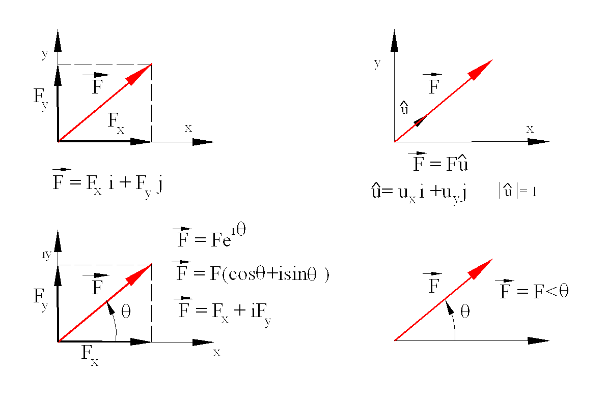
Force is a vectorial quantity that has magnitude, direction and point of application. It can be treated as any other vector quantity. If the equilibrium of the rigid body is our only concern, the point of application of a force is not important. Note that this will not be correct when the internal stress of a rigid body is considered or when the body under consideration is not rigid.
A force in space can be represented by using unit vectors directed along the co-ordinate axes of an arbitrary rectangular reference frame. A unit vector in the direction and sense of the force can also represent it.
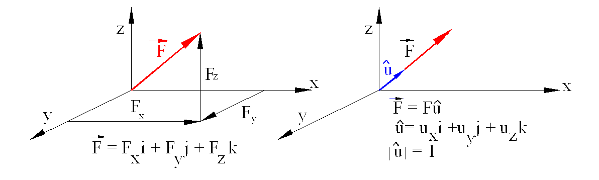
Different forms of representing a planar force are shown below :
Addition and subtraction of concurrent forces (forces whose lines of action intersect at one point) obey the parallelogram law of addition that is schematically shown below. The addition can be carried out graphically by placing the force vectors one after the other in head-to-tail fashion, in which case half of the parallelogram is drawn.
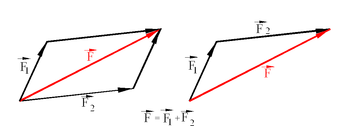
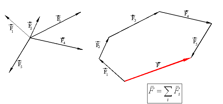
For a system of concurrent forces, the parallelogram law of addition can be applied for the forces in pairs. Alternatively the resultant of the system of forces can be determined using a force polygon . If all the forces lie in a plane, then the resulting force polygon is also plane; otherwise a spatial force polygon will result. The parallelogram law of addition results with the addition of the components of the forces along the axes:
If there are two equal and opposite forces whose lines of action are parallel to each other, the resultant of these two forces is known as a couple
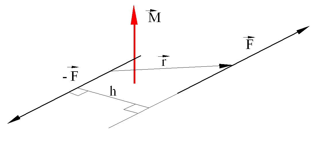
The arm of a couple is defined as the perpendicular distance, h, between the two lines of action. The moment of the couple is another vector M that is normal to the plane of the couple and is in accordance with the right-hand rule. The magnitude of the moment is given by the product: M=hF. The moment vector can be determined by the vectorial product: (M=rxF) Where r is the position vector from a point on the line of action of F to another point on the line of action of F. Note that:
a) The moment vector does not have a point of application. Hence, it is a free vector.
b) The relative position vector, r, is in between any two points on the lines of action of the forces forming the couple.
c) The force couple that creates a moment M is not unique, e.g. there are other force couples that may create the same moment.
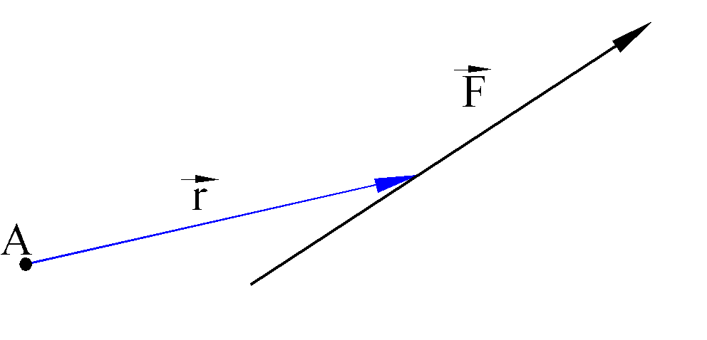
We also define the moment of a force about an arbitrary point with the vectorial product:
M = r x F
In case of nonconcurrent force systems, the system of forces can be reduced to a force acting at an arbitrary point and a moment.
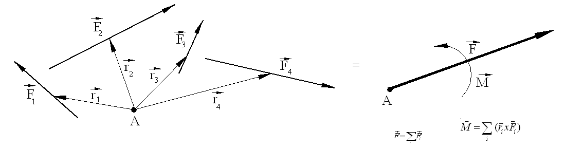
The resultant force and moment are given by the equations
![]()
![]()
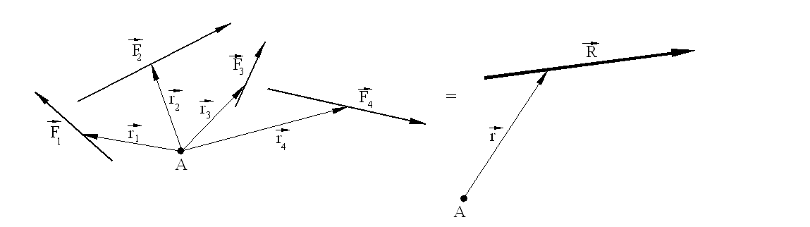
The resultant, F, is as if the forces were concurrent at a point. However, there is also a moment M acting at the particular point considered. The system of forces can further be reduced to a single force, R, provided that the moment of this force about an arbitrary point is equal to the moment of the system of forces, e.g., where r and ri are the position vectors of the resultant and the forces from an arbitrary point A
The magnitude and direction of R can
be determined from the force polygon as if all of the forces were concurrent.


![]()
![]()
![]()
![]() ©es
©es