7.6 Straight Line Motion Mechanisms -2
Straight Line Motion Using in line slider Crank Mechanism
Figure shows an in-line slider-crank mechanism. If the link lengths are properly proportioned, coupler point C will trace an approximate straight line with length s and with maximum deviation of the coupler curve from a straight line being x for a crank rotation f. The coupler curve will be on the approximated straight line only at four positions. However, its deviation from this line at any other position is quite small and in many applications this curve can be used as an approximate straight line.
Furthermore, in such mechanisms when point C is approximating a straight line the motion of the slider is quite small. Hence, the straight line path of point B can be replaced by a circular arc with center B0. This circular arc is achieved by attaching a crank BB0 (note that if BB0 is infinite, than it is the original slider-crank mechanism)
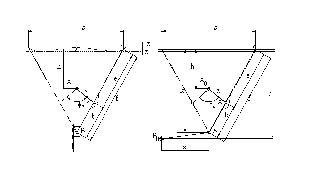
Using the nomenclature ofshown on the figures, and using the conditions for minimum deviation from a straight-line, the following equations can be derived:

These equations give the relation between the design parameters a,b,e and The above relations can be represented in a Chart form as shown in Chart 4. Note that there are four different regions on this chart depending on the location of the coupler point C as shown in. The sign of the parameters a, b and e must be selected accordingly. Let us explain the use of this chart and how the above equations can be solved by an example,

Example
In a design problem it is necessary to replace the slider of a piston pump by a straight line mechanism. The pump stroke is s = 250 mm and due to space limitations the coupler length, f, must be less than 400 mm (say f = 360 mm) and the length h =110 mm.
Using s = 250 mm and f = 360 mm, we have f/s =1.440. Since the error x is going to be rather small, we can assume m ![]() f - h =360-110 =250 mm, Hence, m/s
f - h =360-110 =250 mm, Hence, m/s ![]() 1.00. With the values of f/s and m/s we refer to Chart 4 and obtain (Using Type I). :
1.00. With the values of f/s and m/s we refer to Chart 4 and obtain (Using Type I). :
![]() 0
= 590
0
= 590
x/s![]() .0002
x
.0002
x![]() 0:05
mm
0:05
mm
a/s![]() 0.42
a
0.42
a![]() 105
mm
105
mm
b/s![]() 0.58
b
0.58
b![]() 145
mm
145
mm
Rather than using the charts one can obtain a more exact solution using the formulas and perform linear iteration for a solution. The values f = 360 mm, h=110mm, and s = 250 mm are given. Assume m ![]() f - h =250 mm as the initial guess for m. Calculate k, x, b, e and a from equations 1-6. Next, determine s using eq. 7 . If (sreq-scalc)< e stop . Otherwise compute m=a+b and recalculate x, b, e and a. The iteration steps are shown below. Note that the solution converges in 4 iterations. After a solution is found, one can than calculate l and y using equations 9 and 10.( l = 348.8009, y= 58.58830)
f - h =250 mm as the initial guess for m. Calculate k, x, b, e and a from equations 1-6. Next, determine s using eq. 7 . If (sreq-scalc)< e stop . Otherwise compute m=a+b and recalculate x, b, e and a. The iteration steps are shown below. Note that the solution converges in 4 iterations. After a solution is found, one can than calculate l and y using equations 9 and 10.( l = 348.8009, y= 58.58830)
| s= | 250.00000 | |||
| f= | 360.00000 | |||
| h= | 110.00000 | |||
| k= | 337.60184 | |||
| 1 | 2 | 3 | 4 | |
| m= | 250.00000 | 250.33558 | 250.33483 | 250.33483 |
| x= | 0.33558 | 0.33483 | 0.33483 | 0.33483 |
| b= | 146.30371 | 146.42569 | 146.42541 | 146.42541 |
| e= | 213.69629 | 213.57431 | 213.57459 | 213.57459 |
| a= | 104.03187 | 103.90914 | 103.90942 | 103.90942 |
| scalc= | 261.20837 | 249.97397 | 250.00006 | 250.00000 |
Instead of the slider, we can attach a crank at point B. Taking z = 200 mm we have BB0 = 200.157 mm. We have a four-bar mechanism that generates the required straight-line motion. However, the solution is not yet complete. Point C will trace an approximate straight line only for 58.590 of crank rotation. In order to replace the slider-crank arrangement of the piston pump, point C must only move up and down on this segment. If we let the crank A0A to have a full rotation, the path of point C will be a D shaped curve and it will only move on a straight-line when it is moving downward or upward (depending on the direction of rotation of the crank). This can be eliminated if we can have the crank, AA0, oscillate within 58.590 . This can be achieved with a four-bar mechanism with crank rocker proportions that has link AA0 as its output (rocker) link. If we also require a time-ratio of unity (time for downward stroke = time for upward stroke), then we require centric crank-rocker mechanism. Referring to the design of crank-rocker linkages, and selecting the initial crank angle b=300(y = 58.58830 f=1800 )we obtain the link lengths of the crank-rocker mechanism as a1=1, a2= 0.28052, a3= 0.86603 , a4= 0.573316 . Since a4=a=103.91 mm, a1= 181.24 mm, a2= 50.84 mm , a3= 156.96 mm (mmin= 55.600). The resulting mechanism is a six-link mechanism that has revolute joints only. The result is shown below. Such a mechanism may be cheaper to produce and be more reliable than a slider-crank mechanism (of course, this statement depends on the design problem that is being considered. The reverse may also be true).
![]()
![]()
![]()
![]() ©es
©es