3.3 Coincident Points
In mechanisms we are not involved with the motion of one rigid body but of several rigid bodies. From the corollaries obtained for rigid bodies in plane motion, we can assume that each link in a mechanism is a plane of infinite dimensions which may be represented by a straight line. The relative motions of these links with respect to each other is governed by the joints that connect them. These planes are assumed to be superimposed on top of each other as shown below
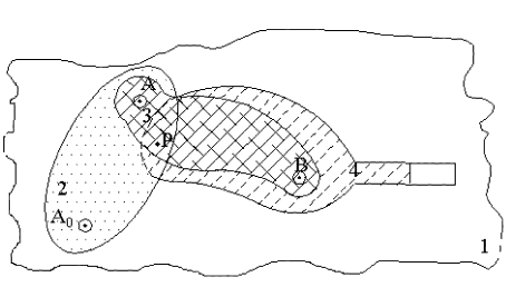
Consider the motion of link 2 with respect to link 1. It will be a rotation about the axis of the revolute joint connecting these links, A0. The size of the joint or the shape of the joint is completely unimportant and, furthermore, it does not matter which link is fixed since we are concerned with the relative motion only. The relative motion between links 2 and 3 or 4 and 3 will again be a rotation about A or B respectively. The relative motion of link 1 with respect to link 4 will be a translation due to the nature of the joint between these two links.
Consider a general point P. In order to locate this point, let us assume that we have pierced a hole through all of the four planes involved. There will be a corresponding point P1 on plane l, P2 on plane 2, P3 on Plane 3 and P4 on plane 4. At the position considered, all these four points are coincident but at any other position these points will be at different relative positions. Consider point P2. It will trace a circle with origin A0 on plane 1 and it will trace another circle with origin A on plane 3. The path of P on plane 4 will not be a circle but a higher order curve (it is a fourth-order algebraic curve in general).
Let us now consider point B. There will be four corresponding points B1, B2, B3 and B4. Since B is on the axis of the revolute pair joining links 3 and 4, B3 and B4 will be coincident at all positions. Such points (B3 and B4) will be called permanently coincident. Where as the other points (B1 and B2 ) are instantly coincident with B3 or B4.
It is not customary to draw mechanisms as shown in the
above figure. Especially for the kinematic analysis, we indicate each
link simply by straight lines or by simple geometric figures. But each
link must be thought as infinite plane at all times. Furthermore, when
we place a point on the plane of a mechanism drawing we must indicate
which plane(s) it corresponds to, unless it is clear due to the mechanism
representation. ![]() For the kinematic analysis please remember that each link is a plane of
infinite dimensions
For the kinematic analysis please remember that each link is a plane of
infinite dimensions
![]()
![]()
![]()
![]() ©es
©es