3.8 Numerical Solution of the Loop Closure Equations
The equations derived in the previous sections for position analysis can easily be used to obtain numerical results when the values of the link lengths are known. One can use a scientific calculator to compute the values of the dependant variables for a given value of the input parameter. If the analysis for the whole range of the input variable is to be performed, some means of programming or a package programme may be useful. In this section examples for different ways of numerical solution will be shown using.
- Scientific calculator,
- Spread-sheet package program such as EXCEL®
- A programming language such as BASIC, PASCAL, FORTRAN or C,
- A package program for solving equations such as MathCAD® or MATLAB®
It must be noted that the numerical solution of mechanisms is not restricted by the examples shown. Advances in the programming techniques and hardware has a great influence on the numerical methods and new software and hardware capabilities may change the approach while keeping the basic mathematics the same.
Teaching a programming language or a package program is our aim. Therefore it is strongly recommended to the reader to refer to any one of the well written texts for a programming language or package program for a complete understanding of commands and features of these programs.
Example 1
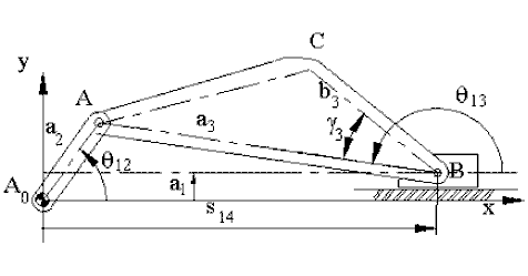
For the mechanism shown :
a2=50 mm; a3= 250 mm; b3=120 mm; a1= 20 mm and g3 =300
Determine the co-ordinates of point C when q12 =600 .
.
Since:
![]()
![]()
which yields q13=5.30 or 174.70
From the figure, we note that we must select q13=174.7 0. Then:
![]()
![]()
![]()
![]()
![]()
![]()
If the calculator is programmable, the above equations can all be programmed as successive operations and the co-ordinates of point C can be obtained for different crank angles. Otherwise, the same calculation must be typed several times. The values of the fixed parameters and the input parameter must all be stored and recalled when necessary. The computation will very much depend on the calculator that is available.
Example 2
Consider the four-bar mechanism shown which has the link lengths:
a1=70 mm; a2= 35 mm; a3= 62.3 mm; a4= 56 mm; BC= c3 = 84.1mm; AC = b3 = 126.6mm
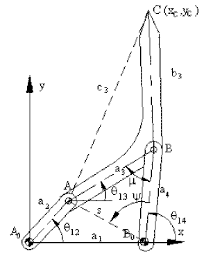
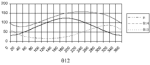
You are to determine q13, q14 and the co-ordinates of point C for 00< q12< 3600with 5 0 increments. The necessary equations are:
xa = s cosf = a2cosq12-a1 = Horizontal component of AB0
ya = s sinf = a2sinq12 = Vertical component of AB0
![]() = magnitude of AB0
= magnitude of AB0
f = tan-1(xa, ya) = angular position of AB0 with respect to positive x axis.
![]() = < ABB0
= < ABB0
![]() = <AB0B
= <AB0B
q14 = f-y
q13 = q14-m
xc = xa + a1 + b3 cos(g+q13)= Horizontal component of the distance A0C.
yc = ya + b3 sin(g+q13)= Vertical component of the distance A0C.
Where:

For this example we will use of EXCEL, a spread sheet program. In a spread sheet program you have a number of cells which can be considered as small boxes. Each cell is in a certain column (designated by letters) and a certain row (designated by a number). Thus a cell has a name such as A1 (first row first column) or C25 (25th row third column), etc. For each cell you can place some number or you can compute and place a new number generated from the numbers which are already placed into other cells. During this computation besides the simple mathematical operations such as addition and multiplication, the spreadsheet has several built-in functions. For example you can square the content of the cell A1 and multiply it will the cosine of the content of the cell A2 and place the new computed number into cell A3. Now, this future can be used very effectively for the analysis of mechanisms.
Place the values of the fixed link lengths a1, a2, a3, a4 into cells A1 to A4 respectively. Into the cell A10, place the value of the angle q12 (0). Now multiply the value in cell A10 by p/180 to obtain q12 in radians and place it into the cell B10 by simply typing =A10 * PI ()/180 into the cell B10. (all the angles must be in radians). You can also convert the angle in degrees into radians by using the build-in function in Excel “RADIANS()” by typing “=RADIANS(A10)” into cell B10. Eq (a) is typed into the cell C10 by typing “=$A$2*cos(B10)-$A$1”. The $ sign must be used for fixed lengths ($ sign in front of column or row designation fixes that row or column. If $ sign is placed on both column and row that cell is fixed. i.e. the cell address becomes an absolute address instead of relative cell address. This is important when the cells are to be copied into other cells Instead of typing the dollar sign, after the cell name is typed you can press the “F4” key). In a similar fashion, you can type in all the formulas from B10 to M10 as shown in row 8 of the spread-sheet , remembering that the formulas are to be solved from top to bottom and from left to right. Normally you will see the resulting numerical values in the cells. Once these equations are typed, if you change the value of q12 in cell A10, the remaining dependent variables will all change automatically. Thus, you can determine the value of q13 , q14 , and the coordinates of point C for any value of the input crank angle.
Now, let us place a different value of q12 into the cell A9. Next use COPY and PASTE option in the EDİT menu to copy the contents of the cells from B10 to M10 into the cells B11 to M11. Note that the formulas will be copied and if you have not fixed the cell with the $ sign, what is A10, B10...F10 in the equations will all be A11, B11,...F11 in this row while $A$1 is kept the same. Next, let us place values of for every 150 increments from 00 to 3600 in column A starting with A10 (you can use 10 interval as well. The only reason why 150 interval is used is to show the result on one screen only.) and copy the formulas in row 7 into all the rows . You will thus obtain
the value of all the dependent variables and the co-ordinates of point C for every crank angle you have selected!
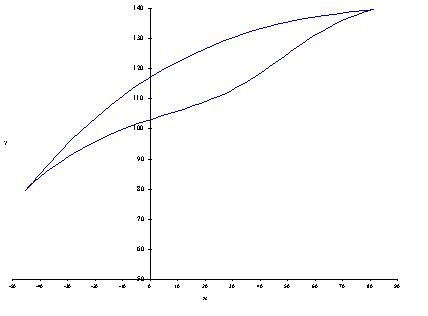
In order to visualise the motion, one can use the chart option of the spread-sheet program and plot q13, q14 and m as function of q12, or plot yc versus xc to determine the coupler path C as shown in the following figures
Note that one can use the closed form method instead of step-wise method as well.
To simulate the mechanism, let us also copy cells A10 to M10 into cells A6 to M6. We shall use the Control Toolbox feature of Excel. Usually the toolbox is not switched on. To switch this toolbox on, click “tools-customize” menu, place a check mark on “Control Toolbox” (You can also place a check mark on “Visual Basic” since we shall utilize this toolbox as well). First click onto the blue triangle-yellow ruler icon to switch to the design mode. There are several different buttons that can be used. We shall use the “Spin Button” which has two arrows up and down. If you are in the design mode, when you click onto the spin button the arrow cursor will change to plus sign. When you are near the cell A7 Right click on the mouse button and form a rectangular box . You will see that the spin button will be formed when you release the right button of the mouse. Right click onto this button shape you have formed and from the pop-up menu select “properties”. You can change the colour, size of the button. One important feature is that you can link this button to a cell. In the “Linked Cell” box type A6, the cell which contains the value of the independent variable (crank angle in degrees). Into the “Max” cell type “360” and into the “SmallChange” cell type an integer step size (say 2). Close the menu and on the Control ToolBox click onto the Blue Triangle icon to close the design mode. İf you click the left arrow on the spin button the value in cell A6 will decrease by 2 and if you click the right arrow, it will increase by 2 and the cells B6-M6 will also change accordingly.
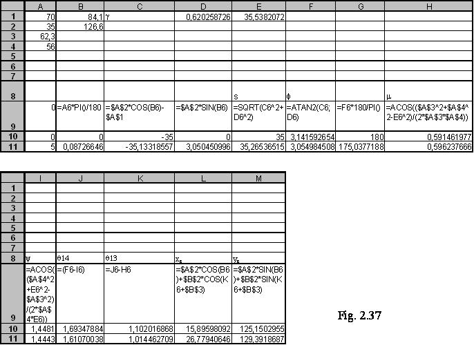
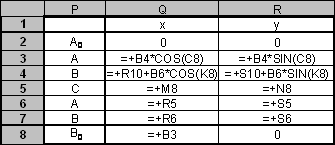
Let us now go to the cell Q2 and R2 and Type 0 , 0 as the coordinates of A0. Next into cell Q3 and R3 type the coordinates of point A which is “=A2*Cos(B6)” and “=A2*Sin(B6)”. Into cells Q9, R9 type the coordinates of point B0 (“=A1” and “0”). Type the coordinates of point B into cells Q4 and R4 as “=Q9+A4*Cos(J6)” and “R9+A4*Sin(J6)”. If you type “=L6” and “=M6” into the cells Q5, R5 you have copied the coordinates of point C into these cells. Into the cells Q7, R7 and Q8, R8 copy the coordinates of points A and B Thus obtaining a table as shown in the following figure (actually in the cells you will be seeing the result as numbers). These are the coordinates of the relevant points on the mechanism.
Next click on the chart icon. Select “XY Scatter” as the Chart type. As sub-type select “scatter with data points connected by lines” and click next. Select series and add series. For x values, select cells Q2 to Q8 which are the x values of points A0ABB0 and C. For y values select cells R2 to R8 which are the y values. You will obtain a chart similar to the one as shown below.
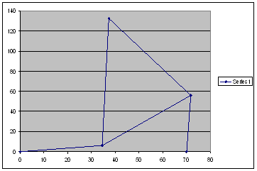
Although the four-bar mechanism is drawn, figure is not exactly satisfactory. First click on the chart and select Chart options from the pop-up menu. Select gridlines for both x and y axes. From the pop-up menu also select "format plot area"to change the colour of the plot area from grey to some other colour (say no colour). Next click on the x and y axes and on the scales menu change the minimum and maximum -40<x<100 and -40<y<140 and change major unit to 20 for both x and y axis. On the screen try to make the grid lines look as a square. In such a case you have made the x and y axis scales the same and the mechanism proportion is more real. Left Click on the mechanism link and select “Format Data Point”. In “Patterns” menu select the colour and the weight of the line that represents the links. For the marker shape select the circle and for the foreground select “No Colour”. These circles will represent the revolute joints between the links. You can also plot the coupler curve shown in Figure as another series on this chart. Now the mechanism will be seen as shown. When you click on the spin button, the input crank angle value will change and so will the positions of all the links of the mechanism drawn on the chart. You can also use different colours for each link by defining A0A, ABCA and BB0 as different series.

Click here to download the Excel file for this example
The analysis and simulation of mechanisms using Excel is explained in more detail in Appendix II.
Example 3.
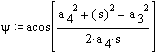
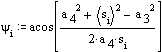
In this example we shall use MathCAD® which is a program for solving equations. There are other programs such as Mathematica® ;, Eureka® ;, MATLAB® ;, etc. which can essentially perform similar equation solving. In spread-sheet approach on the screen you see the cells and the numbers stored in the cells. In case of MathCAD the same basic idea is utilised. However the cells or boxes in which you store the numbers are not shown directly but they exist as a label name that the user assigns. For example, when you type: a:=120 , b:=50, q=20, etc. The program generates boxes with labels a, b, attached to the cells in the computer which stores the values you have typed. (This assignment is done by typing the label and then typing “:”, from which you see “:=” on the screen and the computer expects an assignment to be made to the label typed). There is also a cell with label p which already has the value 3.141592654 that you can use. Similar to the spread-sheet, besides the simple mathematical operations there are several built-in functions as well. Now, if you type: xa:=a*cos( q*p/180)+b on the screen you will see (to type xa type "x.a" on the screen. To type the Greek characters you can use "Greek toolbar" or use [Ctrl] G to change any latin character to its Greek equivalent i.e typing "q [Ctrl] G "will result in " q "
![]()
A new cell with label xa is made available and into this cell the numerical value is placed using the value of the cells a, b and q and the operations indicated. If you want to see the contents of the cell simply type xa =. If you had a:=120, b:=50, q:=20 assigned beforehand, on the screen you will see: xa=143.969. Hence you can see the operations that you have performed as you would write it as a text, and you see the values in certain cells whenever necessary. The formulas that you type are shown in a more realistic form.
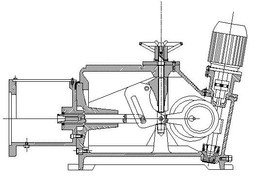
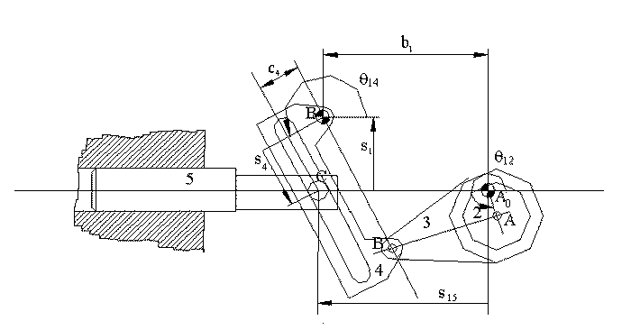
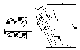
In figure (a) below, an adjustable pump is shown. Crank A0A (which is constructed as an eccentric) is driven by an electric motor through the worm gear. The schematic drawing of the mechanism is shown in figure (b). The stroke adjustment is obtained by moving the location of the pivot point B0 by means of an adjustment screw.
Note that A0ABB0 forms a four-bar mechanism . Unlike the previous examples the fixed link A0B0 is not horizontal and B0 is to the left of A0. We can write the vector equation:
a
b.
B0A= B0A0 + A0A or, equating the real and imaginary parts: |
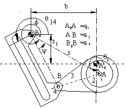 |
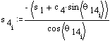
From which we can solve for s and f. Then using the triangle B0A B, the angle y can be determined using the cosine theorem:
Now the angle q14 is: q14= f-y-p/2 For the double slide (links 4 and 5), the loop equation is: which yields:  |
 |
In MathCAD you will write these equations exactly the same way. But before performing any computation, you must define the numerical values of the variables you are going to use either as input or as a result of some computation. The MathCAD sheet for the input crank angle q12 = 1200 will look as follows:
MathCAD Output 1
ADJUSTABLE STROKE PUMP
Determination of the output for a given crank angle.
![]() (to convert degrees into radians)
(to convert degrees into radians)
AoA= ![]() AB=
AB=![]() BBo=
BBo=![]()
![]()
![]()
![]()
![]()
![]()
![]()
![]()
![]()
![]()
![]()
![]()
![]()
![]()
![]()
If we want to analyse the motion for the whole cycle, say for every 50, then we must use indices for the variables so that the computer can allocate several cells to that variable. Secondly, besides obtaining numerical output we can also ask MathCAD to plot the result. In such a case, the solution will be as follows:
MathCAD Output 2
ADJUSTABLE STROKE PUMP
Complete cycle analysis.
![]()
AoA= ![]() AB=
AB= ![]() BBo=
BBo= ![]()
![]()
![]()
![]()
![]()
![]()
![]()
![]()
![]()
![]()
![]()
![]()
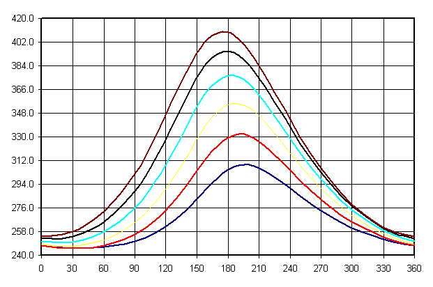
In this case i is not a subscript but an index that tells the computer to allocate an array of cells for that variable with index i. qi is written as q[i not q.i and refers to the ith element of the array qi as in the case of a subscript . If we want to determine the effect of the distance s1 which is adjusted by the screw, to the displacement of the pump, then we must perform the same analysis for different values of s . In this case we must use another index, k. The result is as follows:
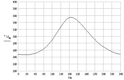
MathCAD Output 3
ADJUSTABLE STROKE PUMP
Analysis for complete cycle and for different strokes.

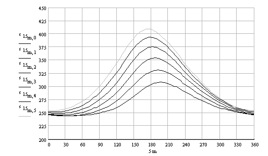
As it can be seen from the figure, as the distance s1 is increased from 50 mm (k=0) to 150 mm (k=5), the stroke changes 63.8 mm (k=0) to 155.4 mm.
You can download the Mathcad file by clicking here
Example 4
The example solved in MathCad can also be solved in Excel. Since the number of steps in the calculation has increased, if we use the Excel sheet only, the number of columns and rows to be used will be large. Instead of using the standard build in functions, we can write a function that will evaluate s16 for a given value of the input angle q12 and adjustment position s1Hence the output parameter value can be evaluated in a single step. From "Tools" menu select "Macro" and then "Visual Basic Editor" . Else you can use Alt+F11 keys. When you are in VBA editor, select "module" from the insert menu. On the module you can write ant VBA program. Let us write a program named AdjustablePump() which will utize the formulas that we have derived. This program may look like:
Global Const PI = 3.1415926
Function AdjustablePump(Crank;Coupler;Rocker;FixedLink_X;Eccentricity;B$7;$A8)
Dim Xa, Ya As Double
Dim S, fi, si, Theta2, Theta4 As Double
Dim S_4 As Double
Theta2 = ThetaDegrees * PI / 180
Xa = FixedLink_X + Crank * Cos(Theta2)
Ya = -AdjustmentLength + Crank * Sin(Theta2)
S = Mag(Xa, Ya) 'BoA distance
fi = Ang(Xa, Ya) 'Angle AB0 makes with the horizontal
Si = AngCos(Rocker, S, Coupler) 'Angle BB0A
Theta4 = fi - si - PI / 2 'Rocker angle
S4 = -(AdjustmentLength + Eccentricity * Sin(Theta4)) / Cos(Theta4)
AdjustablePump = FixedLink_X - Eccentricity * Cos(Theta4) + S4 * Sin(Theta4)
End Function
You can easily follow this function routine. However this function uses three functions which are not available in Excel Library. These are Mag(X,Y) which determines the hypotenuse of a right angled triangle whose two other sides are X and Y. Ang(X,Y) is the same as ATAN2(X,Y) function. The reason we use it is that ATAN2() is not available in visual Basic. AngCos(U1,U2, Opposite) applies the cosine theorem to determine the angle opposite to the side called "Opposite" in a triangle whose other two sides are U1 and U2. Detailed explanation for these functions and more are given in Appendix II. You must insert the Basic.Bas file into your module to use these functions .
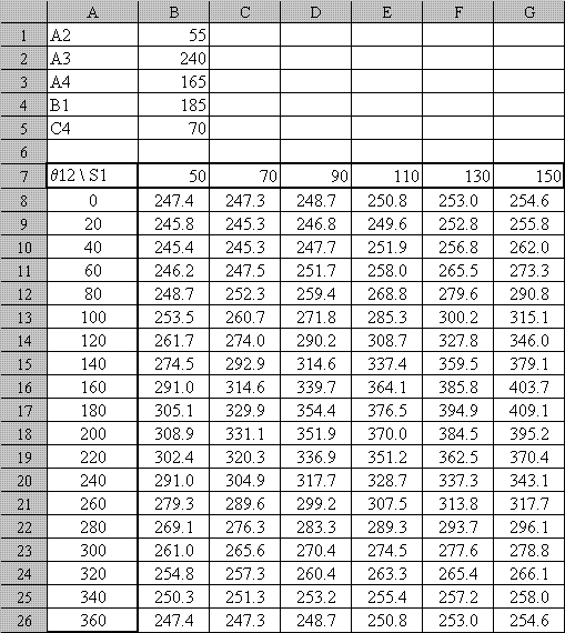
Let us place the values of the link lengths into cells B1 to B5 and name these cells as Crank, Coupler, Rocker, FixedLink_X, and Eccentricity. Into cell B7let us place an adjustment length s1 (s1=20mm).
Next, into cells A8 to A26 let us place the crank angle for every 200 . (after filling the values to the first two-three cells, click right button of the mouse, hold and pull it down up to A26))
Now click on to the cell B8 and into this cell write. = AdjustablePump(Crank; Coupler; Rocker; FixedLink_X; Eccentricity; B$7; $A8 )(you can also use "Insert-Function-User Defined" commands to reach this function and fill in the required parameters) Once you enter this function the position of the plunger (s15) will be determined for the given link lengths, the crank angle in A8 and the adjustmant length in cell B7. If you copy This cell (B8) up to B26, you will be able to determine the plunger position for every crank angle and for the given adjustmant length B7, since when during vertical copying the cell B/ does not change since we have fixed the row as B$7.
The distance s 1 is changed by an adjustment screw shown. If we want to determine the effect of this adjustment, s 1, on the displacement of the plunger, s15 , into cells B7, C7, D7, E7, F7 and G7 we place different values of s 1. Since the value of s 1 in cell B7 is written as B$7 row 7 does not change (whereas in column C B$7 will be C$7). Now copy cell B8 horizontally from B8 to G8 and then verticall up to G26. Each column will refer to a particilar adjustmant s 1 and each row will refer to a particular crank angle q12 The result is given as a Excell sheet and sketch below. You can download the Excel file.
If your company is producing such a pump with different size, everybody in the company can make use of such a file very easily!!!
A note on the accuracy of computation.
In the computers the numbers are stored using finite number of digits. For example in MathCAD, all the computations are performed in 15 significant digits. In certain other programs or compilers the number of digits may vary from 6 to 32. In mechanism analysis the number of significant digits used by the hardware or software is more than sufficient and very precise results can be obtained. The exceptions are when the mechanism is at or near a dead centre position, in which case the precision may decrease or an error command may be displayed (such as division by zero or negative value in the square root). This will also indicate a misbehaving mechanism in practice.
In engineering computations “No result can be more accurate than the accuracy of the input parameters”. Therefore, your result must not contain more significant digits than the number of significant digit for the input parameters. For example, if you are to manufacture the links using classical tools in a machine shop and if the accuracy of the link lengths are within ±.1mm, an x displacement result cannot be x=26.231456789mm. This must be rounded to x=26.2 .
![]()
![]()
![]()
![]() ©es
©es