4.1 VELOCITY AND ACCELERATION ANALYSIS - 2
General Plane Motion:
General plane motion is the plane motion which is neither translation or rotation about a fixed axis but it can be analysed by the superposition of these motions using the relative motion concept.
Consider a plane represented by two points AB. Finite displacement of the rigid body from position 1 to position 2 at a time interval t can be regarded as the sum of the translation from AB to A’B” and a fixed axis of rotation about an axis perpendicular to the plane and passing through A’. One can also achieve the same final motion by translating from AB to A”B’ and then rotating about an axis passing through B’, or one can first perform a rotation about an axis perpendicular to the plane and passing through any point on the rigid body and then perform the translation. The actual paths of points will of course not correspond to the paths described by these different combinations of rotations and translations, but the final position can be reached and when the two positions are infinitesimally close these motions will coincide with the instantaneous paths of the points on the rigid body.
When performing translation, every point on the rigid body moves with the motion of the point selected and the velocity and acceleration of every point is the same for this motion. In case of rotation the rigid body is rotated about an axis passing through the particular point selected for translation. Now the rigid body is in a rotation. Since the point selected is not fixed, it is a relative motion.
General Plane motion seperated to translation and rotation.
Let us analyse this relative motion by attaching a moving reference frame x-y at point A, that translates relative to the fixed frame X-Y .The motion is to be considered of two parts. First, the body translates from AB to A’B” with displacement Dr A which is the displacement of point A. This is similar to the rigid body translation discussed in part (a). Next the body rotates by an angle Df about A’. Since the distance of any other point, such as B, remains constant, the motion of B from B” to B’ will be on an arc with centre A’ and will be displaced by Dr B/A . This displacement is the motion of point B relative to point A.
The total displacement of point B will be the sum of these two motions:
Dr B = Dr A + Dr B/A
Since the motion from B” to B’ is a rotation, Dr B/A = |BA|Df. Note that this relative motion is a function of absolute instantaneous angular motion Df of the rigid body. Therefore selection of point A will not effect this angular rotation, whereas the translation will depend on the point A that is selected. If one changes the order of rotation and translation the same equation will result. Dividing the above equation by the corresponding time interval, Dt and taking the limit as Dt tends to zero we obtain:
V B = V A + V B/A
where
V B/A =wx r B/A
and
r B/A = AB = r B - r A
V B/A is a relative velocity between two points B and A belonging to the same rigid body. V B and V A are absolute velocities of points A and B on a rigid body in a general plane motion.
The same result can be obtained using complex numbers by writing the position of point B relative to A in complex numbers:
r B = r A +be if
where b= |AB| and f is the angle between the line AB and the positive real axis. b if term shows the position of point B with respect to A and b length is constant only if both A and B are on the same rigid body. Since we are to be concerned with the relative motion, let us assume that the velocity and acceleration of point A is known. (V A and a A are known). Differentiating the above equation with respect to time:
V B = V A +ibwe if
where w=df/dt. The second term has the magnitude bw and is in the direction ie if , which is a unit vector perpendicular to AB rotated in the sense of w. This is the relative velocity of point B with respect to A (Fig.4.60). Hence:
V B/A = ibwe if
and
V B = V A + V B/A
Velocity of point B in terms of velocity of point A.
Differentiation of the velocity equation with respect to time yields:
a B = a A +ibae if -bw 2e if
Acceleration of point B in terms of acceleration of point A
The first relative acceleration component has the magnitude ba and is in the direction ie if (Fig.4.61), which is perpendicular to the line AB and rotated in the sense of the angular acceleration a. This is relative acceleration component is tangential relative acceleration component and is denoted by a t B/A . The second relative acceleration component has the magnitude bw2 and is in the direction -eif which is along the line AB towards the centre of rotation A. This direction is normal to the relative path of B with respect to A. Therefore it is called normal relative acceleration component and is denoted by a n B/A. Hence the acceleration of point B can be expressed as:
a B= a A+a t B/A+a n B/A
and the relative acceleration is:
a B/A= a t B/A+a n B/A
Therefore, for the relative motion between two points on a rigid body in a general plane motion the relative velocity and acceleration components are as if the body is in a fixed axis of rotation about one of the points on the rigid body.
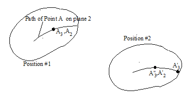
Another different type of relative motion occurs between two coincident points on two different rigid bodies but for which we know the path of one point relative to the other rigid body.
Consider plane 2 moved from position #1 to another position #2. During this time a point A3 that is coincident with A 2 at position #1 but on a different plane, moves to position A’ 3 while A 2 moves to A’ 2 . Points that were instantaneously coincident in position #1 are not coincident at position #2. However, the path of on link 2 is known. The motion of point A 3 can be regarded as the sum of translation with A 3 to A” 3 that is coincident with A’ 2 and a relative motion from A” 3 to A’ 3 relative to the plane 2. Hence, as shown below, point A 3 first moves by a distance Dr A2 with A 2 and then moves by a distance Dr A3/2 relative to A 2 . The order of the two superimposed motions is not important.
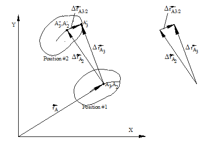
The total displacement of point A3 is:
Dr A3= Dr A2 +Dr A3/2
Dividing the above expression by the corresponding time interval, Dt , and taking the limit as Dt tends to zero, we obtain:
V A3= V A2 +V A3/2
where V A3/2 is the relative velocity which is always tangent to the relative path of point A 3 with respect to the plane 2.
In mechanisms such relative motion occurs when we have prismatic, cylinder-in-slot or cam pairs between two moving links. In case of cam pairs we utilise equivalent linkage concepts with which we can replace a cam pair instantaneously by an equivalent mechanism containing lower kinematic pairs (see section 2.3). For prismatic or cylinder-in-slot joints, the relative path is a straight line.
In order to explain the relative motion between the two links, consider link 3 connected to link 2 by a prismatic joint . For simplicity, link 2 is connected to the fixed link by a revolute joint. Point B corresponds to two coincident points B 2 and B 3 on links 2 and 3. The position vector for point B (B 2 or B 3 ) in complex numbers is:
R B=re iq
Note that R B is the position vector for both B 2 and B 3. However for B 2 r is a constant but for B 3 r is a variable. Therefore, when differentiating this vector, we must specify which rate of change of position is sought. For example if we are to determine the rate of change of the position of point B 2, then:
V B2= irwe iq
where w=dq/dt . If we want to determine the rate of change of the position B 3, then:
![]()
The first term is the velocity of point B 2 ,V B2. The second term is the relative velocity of point B 3 with respect to link 2. It is tangent to the relative path. Hence:
V B3= V B2 +V B3/2
B 3, which is fixed on link 3 will be coincident with another point B’ 2 on link 2 after a certain time interval. The second derivative of the position vector with respect to time yields:
Where the terms in the first bracket are those obtained from the differentiation of V B2 , and those in the second bracket are obtained when the relative velocity V B3/2 is differentiated. The first two terms are the tangential and normal accelerations components of point B 2 and they add up to the angular acceleration of point B 2 (a B2). The third term arises due to the fact that B 2 observed as the coincident point with B 3, will be a different point in a differential displacement. At a certain time interval Dt, B 3 will be coincident with B’ 2, that is at a distance Dr from B 2 (direction being along the axis of the slider) . The velocity of B 2 is ![]() and the velocity of B’ 2 is
and the velocity of B’ 2 is ![]() . The change in the velocity during the time period Dt is
. The change in the velocity during the time period Dt is ![]() . Therefore there is an acceleration perpendicular to the slider axis by an amount
. Therefore there is an acceleration perpendicular to the slider axis by an amount ![]() .
.
Consider the terms obtained when the relative velocity is differentiated. The first term is due to the change in magnitude of the relative velocity. This term is tangent to the relative path. The second term is due to the change in the direction of the relative velocity vector. In order to explain this term consider a constant magnitude for relative velocity. At a certain time interval Dt, link 2 will rotate by an angle Dq. The direction of the relative velocity is now ![]() instead of
instead of ![]() initially. The vectorial change of the relative velocity vector is
initially. The vectorial change of the relative velocity vector is ![]() , and its time rate of change is
, and its time rate of change is ![]() . The last two terms in both of the brackets are the same in magnitude and direction. They can be combined into one term
. The last two terms in both of the brackets are the same in magnitude and direction. They can be combined into one term ![]() This term is called Coriolis acceleration component and is represented by a cB3/2 . It is a relative acceleration component. Its direction is normal to the relative path described by B 3 on link 2. Its direction is obtained by rotating the relative velocity vector V B3/2, 90 0 in the sense of the angular velocity of link 2. Hence the acceleration of point B 3 can be written as:
This term is called Coriolis acceleration component and is represented by a cB3/2 . It is a relative acceleration component. Its direction is normal to the relative path described by B 3 on link 2. Its direction is obtained by rotating the relative velocity vector V B3/2, 90 0 in the sense of the angular velocity of link 2. Hence the acceleration of point B 3 can be written as:
![]()
![]()
In the previous case, since the prismatic joint axis is along the radial line B 0B, the normal acceleration component of point B 2 (an2) and the tangential relative acceleration component atB3/2 are along the same direction (so is a cB3/2 and atB2). These directions need not be along the same direction in general. Consider a prismatic joint as shown in figure below between links 2 and 3. In such a case:
![]()
where b and a are fixed parameters of link 2. Differentiating, we obtain:
![]()
which can be written in the form:
![]()
Note that:
![]()
.
Where b is the variable distance A0B and g is the variable angle between A 0A and A 0B on link 2. This vector is the position of point B on a coordinate frame fixed on link 2. Hence:
![]()
or
V B3= V B2 +V B3/2
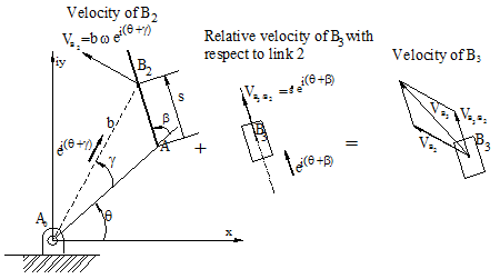
The first term has the magnitude w|A0B|= wb and its direction is perpendicular to the line A0B since the unit vector is ie i(q+g) . The second term has the magnitude ![]() which is the relative velocity of point B3 with respect to link 2 and its direction is along the slider axis AB given by the unit vector e i(q+b ).
which is the relative velocity of point B3 with respect to link 2 and its direction is along the slider axis AB given by the unit vector e i(q+b ).
Differentiating the velocity equation once more, we have the acceleration of point B3 as
the terms can be grouped as:
![]()
or substituting ![]() :
:
![]()
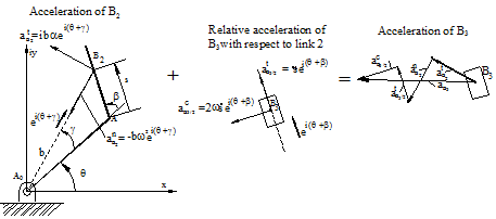
The first two terms are the tangential and normal acceleration components of point B2 whose direction are normal and parallel (directed towards A0) to the line A0B respectively . The third term is the relative Coriolis acceleration which is perpendicular to the slider axis AB (given by the unit vector ie i(q+b) ). The last term is the tangential relative acceleration with magnitude ![]() and direction e i(q+b) which is along the slider axis AB. Therefore in vector form the acceleration of B3 is:
and direction e i(q+b) which is along the slider axis AB. Therefore in vector form the acceleration of B3 is:
![]()
![]()
![]()
![]()
![]() ©es
©es