7.3. INVERTED SLIDER-CRANK MECHANISM

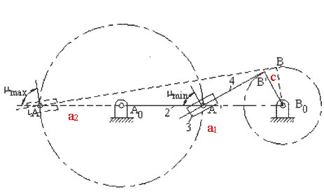
Two different configurations of inverted slider-crank mechanism is shown above. In general, link 2 is the input and link 4 is the output. The prismatic pair is in between the links 3 and 4. The two inverted slider-crank mechanisms shown have the same input-output motion characteristics. However, their force transmission characteristics are different. For the configuration shown in A, transmission angle is shown below. Note that Ft is the force that creates the output torque and F is the force transmitted to link 4. The minimum and maximum values of the transmission angle for this type of inverted slider crank mechanism is when the crank and the fixed links are collinear as shown (similar to the four-bar mechanism). In case of a mechanism shown in B, there is moment transmission between links 3 and 4 rather than force transmission and the definition for the transmission angle given in Section 4.1.3. fails. (There is another type of transmission angle definition that is applicable to such mechanisms. This will be beyond the scope).


An inverted slider-crank mechanism is centric or eccentric depending on the distance BB0 as shown.

Centric Inverted Slider-Crank Mechanism
The dead-centre positions of the centric inverted slider-crank mechanism is easily found by drawing tangents to the circle with radius AA0 from B0 (positions A0A1B0 and A0A2B0 ). Since A0A1B0= A0A2B0 = 900, the following relation holds between the swing angle y and the corresponding crank rotation f:
y + f =1800 (1)
Also note that for link 2 to be the crank (e g. to make complete rotation) a2 > a1. When a1 = a2, we have isosceles inverted slider-crank mechanism.

Eccentric Inverted Slider-Crank Mechanism
For the eccentric inverted slider-crank mechanism, we determine the dead-center positions by drawing inner and outer tangents to the circle with radius AA0 from the circle with radius BB0 (Positions A0A1B1B0and A0A2B2B0 as shown ). Note that the relation y + f =1800 is also true for the eccentric inverted slider-crank mechanism. For a complete rotation of the input crank (link 2) , the inequality:
a2 + c < a1 (2)
must be satisfied.

What we have stated up to now holds true for both of the inverted slider-crank mechanisms. The transmission angle for the first type of the inverted slider-crank mechanism becomes maximum or a minimum when the crank and the fixed link are collinear as shown. The minimum or the maximum value is given by the equation:
![]() (3)
(3)
Note that for centric inverted slider-crank mechanism the transmission angle always keeps the optimum value,900. Because of this characteristics, centric type is usually preferred (such as the quick-return mechanisms). However, one can obtain smaller link-length dimensions with the eccentric type for the same swing angle and corresponding crank rotation. Hence, an eccentric inverted slider-crank mechanism may be advantageous although the transmission angle characteristics of the centric type is optimum. Using the geometry, the relation between the link length dimensions for a given swing angle is:
 (4)
(4)
As it is seen from the above equation, one other advantage of the inverted slider-crank mechanism over the four-bar is the ease of design, since there are less parameters, e.g. if we want a link to swing by a certain angle, one can design an inverted slider-crank mechanism with less labour.

While the first type of inverted slider-crank mechanisms are often used for quick-return motion, the second type are often used in hydraulically actuated mechanisms in which the relative motion at the sliding joint is the input and link 2 is the output. The sliding joint is in the form of piston cylinder arrangement. Typical applications can be seen in all construction machinery, portable cranes, dump trucks, etc. In these applications usually there is no eccentricity, c, since in such a case undesired side forces at the piston will be created. The most common shape is shown in
For a given stroke, s, the output link B0B is to swing by a certain angle y . If we also search for the mechanism in which the force transmission characteristics is optimum, the deviations of the maximum and minimum transmission angles from 900 at the two ends of the stroke must be made equal. Deviation of the transmission angle at the two extreme positions can be made equal only if A0B1 and A0B2 are collinear . In such a case B1B2 = s and the triangle B1B0B2 is an isosceles triangle in which mmin1= mmin2=1800- mmax and mmin=900-y/2. The crank length B0B=a4 must be equal to:
![]() (5)
(5)
 |
 |
If we also let s0 to be the minimum distance between A0B (which is the length of the piston and cylinder in closed form), then the fixed link length A0B0=a1 will be given by:
 (6)
(6)
Usually s0 and s are given in hydraulic piston catalogues. One can then select a1 and a4 to obtain the required swing angle using the selected hydraulic piston.