7.7. COUPLER-POINT CURVE
For the mechanisms considered, the displacement of the links joined with the fixed link was the input or output of the simple mechanisms. In great number of applications the output from a simple mechanism is the path traced by one of the points on the coupler link. These paths are generally called “coupler point curves” or “coupler paths”. In thye following figures coupler point curves for a four-bar, slider-crank and inverted slider-crank mechanisms are shown and some typical examples of using these curves are given. Determination of the link length dimensions to generate a particular coupler curve is beyond the scope. If the link lengths are given, one can easily determine the coupler curve graphically or analytically using the methods discussed in Chapter 2.
Coupler curves of a four-bar mechanism with crank-rocker proportions.
Coupler curves of a slider-crank mechanism.
Coupler curves of inverted slider-crank mechanisms.
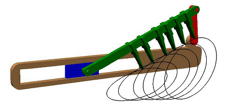
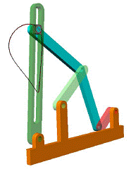
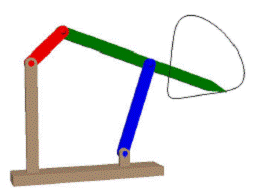
In a the coupler path is used in an agricultural machine to push the hay into a baler. In (b) the due to a straight line motion the output does not have a motion for a certain amount of input rotation (dwell motion) and in (c) two approximate straight lines making an angle with each other is generated by the four-bar.
 |
 |
 |
(a) |
(b) |
(c) |
Examples
![]()
![]()
![]()
![]() ©es
©es