|
Appendix-2 |
Function Routines for Simple Mechanisms and Basic Trigonometry
In practice complex mechanisms are usually formed from the simple four-link mechanism loops connected to each other in series or in parallel. Usually the loops formed form a quadrilateral which can be solved geometrically. If simple function subroutines can be written for the simple mechanisms, these subroutines can be used for the solution of more complex mechanisms. In Excel, these function subroutines can be written in Basic language (Visual Basic for Applications, VBA® for short). Such function subroutines are very important building block for more complex analysis. Similar subroutines can as well be written in C, Fortran, Pascal or in any other computer language. In this appendix several function subroutines which were found to be very useful in mechanism analysis will be explained and using these functions kinematic analysis of mechanisms with several links will be performed.
2.1. Function routines written in Visual Basic for Applications (VBA)
2.1.1 Conversion from rectangular to polar form
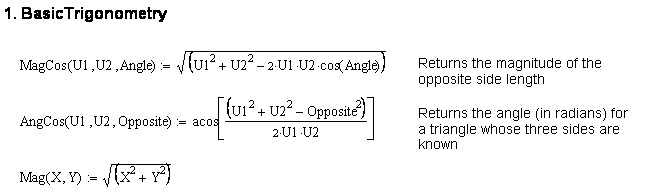
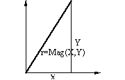
In Cartesian reference the coordinates of a point in plane is given by its x and y coordinates. If we want to determine the distance OP (magnitude of the vector OP), and the angle the vector makes with respect to the positive x axis, we can write two function routines (Mag(x,y) and Ang(x,y)) to determine the magnitude and the angular orientation of the vector OP defined by (x,y) coordinates (see figure). Note that Ang(x,y) function is similar to TAN2(x,y) function in Excel. It uses Atn(x) function in Basic language for the inverse tangent which returns the result within -p/2<q<p/2. Next the the quadrant in which the angle lies is determined from the values of x and y and correct result is given within the range -p<q<p Outside the function routine, two global constants PI and Eps are defined.
Global Const PI = 3.1415926
Global Const Eps = 0.0000001 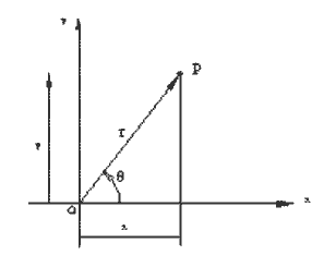
Function Mag(X, Y)
Mag = Sqr(X ^ 2 + Y ^ 2)
End Function
Function Ang(X, Y)
Dim AA
If Abs(X) > Eps Then
AA
= Atn(Y / X)
If
X < 0 Then
AA
= AA + PI
Else:
If
Y < 0 Then AA = AA + 2*PI
End
If
Else:
If
Y > 0 Then AA = PI / 2 Else AA = -PI / 2
End If
Ang = AA
End Function
2.1.2. Inverse Sine and Cosine Functions:
Normally in most languages Atn(x)- the inverse tangent function is defined only. when writing programs in basic, we shall need other inverse trigonometric functions such as ASIN(x) and ACOS(x). Although these inverse functions are double valued, only one result is returned. If the user wants to use the other angle he must add or subtract p to the result.
Function Acos(X)
Acos = Atn(-X / Sqr(-X * X + 1)) +
2 * Atn(1)
End Function
Function Asin(X)
Asin = Atn(X / Sqr(-X * X + 1))
End Function
2.1.3. Triangle Solution (Cosine Theorem):
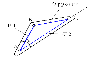
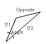
During the analysis of mechanisms solution for a triangle is often used. Using the cosine theorem one can determine the angle when the three sides of a triangle is given (a= AngCos(U1,U2,Opposite)) or one can determine the opposite side when the two sides and the included angle a (ANGLE) is given (Opposite = MagCos(U1,U2;Angle)) (see Figure ) . The following two BASIC functions can give you the result when the three values are given. Note that AngCos() function uses Acos() function which was written in Basic
Function AngCos(U1, U2, Opposite)
Dim u u = (U1 * U1 + U2 * U2 - Opposite
* Opposite) / (2 * u1 * u2)
AA = Acos(u)
AngCos = AA
End Function
Function MagCos(U1, U2,Angle)
MagCos = (U1 ^ 2 + U2 ^ 2 - 2 * U1
* U2 * Cos(Angle)) / (2 * U1 * U2)
End Function
2.1.4. Position Analysis of Simple Mechanisms:
2.1.4-a) Four-Bar Mechanism
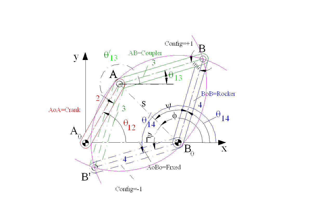
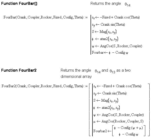
Three function subroutines have been written to determine the unknown position variables in a four-bar mechanism when the link lengths, the configuration in which the links are assembled and the input crank angle are given. All three functions require the same input parameters
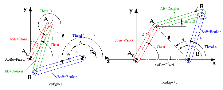
output from the FourBar() function is the rocker angle whereas for FourBarCoupler() it is the coupler angle. In case of FourBar2() function there are two outputs as [Coupler Angle, Rocker Angle] The user must type +1 or 1 for the Config variable depending whether the mechanism is assembled in open or crossed form respectively.
Note that this program uses Ang() and Mag() and AngCos() functions. These functions must be available for this function routine (i.e you cannot use these functions alone).
Function FourBar(Crank, Coupler, Rocker, Fixed, Config, Theta)
'Determines the output rocker angle wr to the fixed link
Dim S, Fi, Si As Double
Dim sx, sy As Double
sx = -Fixed + Crank * Cos(Theta)
sy = Crank * Sin(Theta)
S = Mag(sx, sy)
Fi = Ang(sx, sy)
Si = AngCos(Rocker, S, Coupler)
FourBar = Fi - Config * Si
End Function
Function FourBrCoupler(Crank, Coupler, Rocker, Fixed, Config, Theta)
'Determines the coupler link angle wr to the fixed link
Dim S, Fi, Si, Mu As Double
Dim sx, sy, Theta14 As Double
sx = -Fixed + Crank * Cos(Theta)
sy = Crank * Sin(Theta)
S = Mag(sx, sy)
Fi = Ang(sx, sy)
Si = AngCos(Rocker, S, Coupler)
Theta14 = Fi - Config * Si
Mu = AngCos(Coupler, Rocker, S)
FourBrCoupler = Theta14 - Config * Mu
End Function
Function FourBar2(Crank, Coupler, Rocker, Fixed, Config, Theta)
'Determines the both the coupler link and the rocker angles with respect to the fixed link
'first term is coupler angle
Dim S, Fi, Si As Double
Dim sx, sy As Double
Dim A(2)
sx = -Fixed + Crank * Cos(Theta)
sy = Crank * Sin(Theta)
S = Mag(sx, sy)
Fi = Ang(sx, sy)
Si = AngCos(Rocker, S, Coupler)
Mu = AngCos(Coupler, Rocker, S)
A(1) = Fi - Config * Si
A(0) = A(1) - Config * Mu
FourBar2 = A
End Function
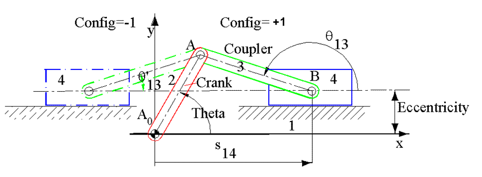
2.1.4-b) Slider-Crank Mechanism:
For the slider crank mechanism shown again three different function programs are written. SliderCrank() gives the slider displacement s14, SliderCrankCoupler() coupler angle q13 and SliderCrank2()) which gives both the coupler angle and the slider displacement [q13,s14] for given link lengths and corresponding crank angle q12 (Theta) . .
The user must type Config as +1 or -1 depending on the position of the slider with respect to the crank.
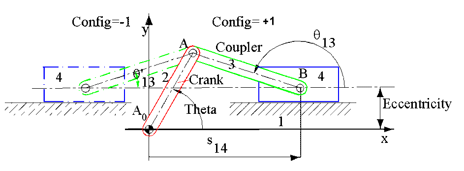
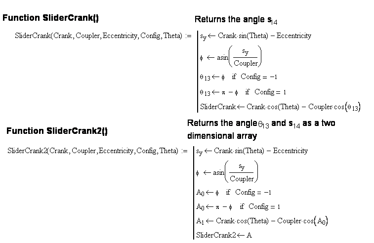
Function SliderCrank(Crank, Coupler, Eccentricity, Config, Theta)
'Determines the slider displacement
Dim Fi As Double
Fi = Asin((Crank * Sin(Theta) - Eccentricity) / Coupler)
If Config = 1 Then Fi = 4 * Atn(1) - Fi
SliderCrank = Crank * Cos(Theta) - Coupler * Cos(Fi)
End Function
Function SliderCrank2(Crank, Coupler, Eccentricity, Config, Theta)
'Determines both the slider displacement and the coupler link angle
Dim Fi As Double
Dim A(2) As Double
Fi = Asin((Crank * Sin(Theta) - Eccentricity) / Coupler)
If Config = 1 Then Fi = 4 * Atn(1) - Fi
A(0) = Fi
A(1) = Crank * Cos(Theta) - Coupler * Cos(Fi)
SliderCrank2 = A
End Function
Function SliderCrankCoupler(Crank, Coupler, Eccentricity, Config, Theta)
'Determines the coupler link angle
Dim Fi As Double
Fi = Asin((Crank * Sin(Theta) - Eccentricity) / Coupler)
If Config = 1 Then Fi = 4 * Atn(1) - Fi
SliderCrankCoupler = Fi
End Function
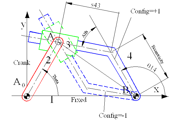
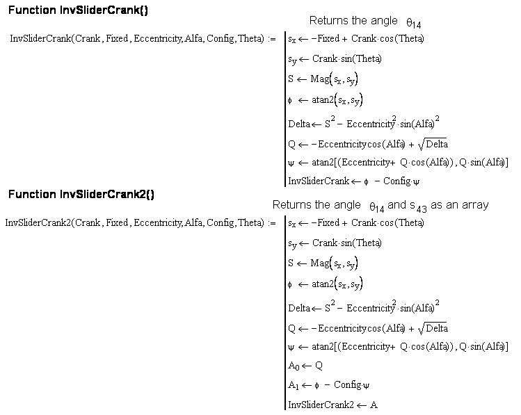
2.1.4-c) Inverted Slider-Crank Mechanism:
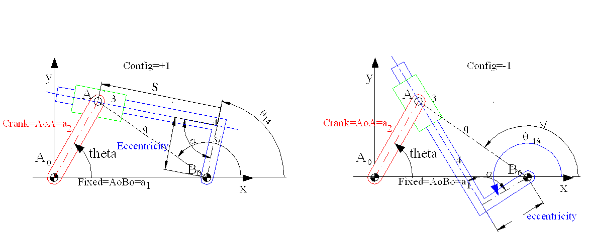
For the inverted slider crank mechanism shown the visual basic function routine is Invslider2(Crank, Fixed, Eccentricity, Alfa, Config, Theta) Config can be +1 or -1 according to the way the mechanism is assembled. This function returns the slider displacement s and the output link angle q14.
Function InvSlider2(Crank, Fixed, Eccentricity, Alfa, Config, Theta)
'Determines the slider displacement and the output link angle for an inverted slider-crank mechanism
'For centric inverted slider you must select both eccentricity and angle alfa as zero
Dim A(2) As Double
Dim S, Fi, Si, Q, Delta As Double
Dim sx, sy As Double
sx = -Fixed + Crank * Cos(Theta)
sy = Crank * Sin(Theta)
S = Mag(sx, sy)
Fi = Ang(sx, sy)
Delta = S ^ 2 - Eccentricity ^ 2 * Sin(Alfa) ^ 2
Q = -Eccentricity * Cos(Alfa) + Sqr(Delta)
Si = Ang((Eccentricity + Q * Cos(Alfa)), Q * Sin(Alfa))
A(0) = Q
A(1) = Fi - Config * Si
InvSlider2 = A
End Function
In case of a centric inverted slider-crank mechhanism the same program can be used by selecting the parameters Eccentricity=0 and Alfa=0 or Another function can be written. Also instead of two outputs you may want to have one output only.
![]() Write a function routine for the solution of a centric inverted slider crank mechanism.(and Call it InvSliderCrankCentric())
Write a function routine for the solution of a centric inverted slider crank mechanism.(and Call it InvSliderCrankCentric())
![]() Write a function routine that gives q14 as the output only (and Call it InvSliderCrank())
Write a function routine that gives q14 as the output only (and Call it InvSliderCrank())
All the above functions are written in Visual basic and is available as Basic.Bas file which you can download here If you want to use these files in an excel sheet, switch to (and Call it InvSliderCrank())Visual Basic editor (From the tools menu select macro and Visual Basic Editor of simply press Alt+F11 buttons) and then from the file menu select "import file" (or Ctrl+M).and import Basic.bas file as a module. Now, when you are on an Excel Sheet you can use any of the above functions (use "insert" menu- "functions" and "user defined" type. You will be able to see all the above functions)
Example
Using these build in functions, analysis of mechanisms with several loops simplify to a very great extent. These functions can be used for the analysis of complex mechanisms.
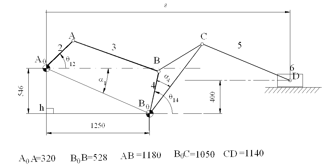
The six link mechanism shown below is composed of a four-bar and a slider crank mechanism connected in series.We are to determine the displacement of the slide s, for a given value of the crank angle th. Once the mechanisms that form the structure are identified, we can break the analysis in two parts. First for a given input crank angle th (link 2) we determine the angular position of link 4 (th4) using the FourBar() function. Next Using (q14-a) as the input crank angle of link 4 we determine the horizontal distance B0D of the slider using SliderCrank() function. s=B0Dx+B0A0x B0A0x=1250 mm given.
On the excel Sheet let us first enter the known link dimensions (lengths and angles).
| A | B | C | D | E | |
| 1 | Four_Bar | Slider-Crank | |||
| 2 | Crank | 320 | Crank 2 | 1050 | |
| 3 | Coupler | 1180 | Coupler 2 | 1140 | |
| 4 | Rocker | 528 | Eccentric | 400 | |
| 5 | Fixed_Lx | 1250 | Alfa4 | 0.43633231 | 25 |
| 6 | Fixed_Ly | 546 | |||
| 7 | Fixed_Link | 1364.044 | |||
| 8 | Fixed Angle | 2.72977 | 156.40429 | ||
| 9 | Alfa1 | 0.411823 | 23.595705 |
From the given x and y lengths (Fixed_Lx and Fixed_Ly) the fixed link length is determined by using the function mag() as mag(B5;B6) in cell B7. in cell B8 we determine the angle B0A0 vector makes with the horizontal using ATAN2() Excel
function in the form ATAN2(-B5;B6). angle Afa1 is obtained by typing "=pi()-B8" into cell B9. In cell E5 the angle
![]() BB0C =Alfa4 is entered in degrees and it is converted to radians in cell D5
. Cells in columns B ve D are named cells whose names are the labels entered left of the corresponding cell (i.e. Cell B7 is named as "Crank", Cell D3 is named as "Coupler_2", etc.)
BB0C =Alfa4 is entered in degrees and it is converted to radians in cell D5
. Cells in columns B ve D are named cells whose names are the labels entered left of the corresponding cell (i.e. Cell B7 is named as "Crank", Cell D3 is named as "Coupler_2", etc.)
Now into cells A16-A40 the input crank angle, Th, from 0 to 360 degrees at 150 interval is entered.
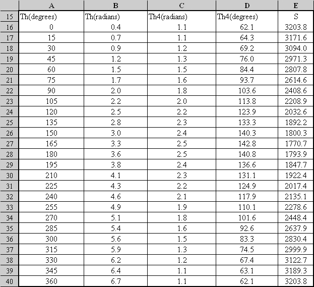
The angle Th entered in column A is q12 shown on the sketch. This is the angle link 2 makes with respect to a horizontal line, not with respect to A0 B0 . In column B after converting q12 into radians the angle Alfa1 Given in cell B9 is added by typing "=A16*PI()/180+Alfa1" into cell B16 and copying this formula from B16-B40. (If you have not named cell B9 as "Alfa1", then you must type $B$9 to fix this cell. Into cell C16 type
"=FourBar(Crank;Coupler;Rocker;Fixed_Link;1;B16)-Alfa1"
or
"=FourBar($B$2;$B$3;$B$4;$B$7;1;B16)-$B$9"
Using the FourBar() function You have calculated the angular position of link 4 with respect to the horizontal, q14 . When the formula is copied for cells C17-C40,q14 is determined in radians for every input crank angle q12 given in column A. In column D you can convert the angle q14 into degrees. Now, we can solve the slider crank mechanism (Links 1,4,5 and 6). Into cell E16 if we type:
"=SliderCrank(Crank2;Coupler2;Eeccentric;1;(C15-Alfa4)) + Fixed_Lx"
or
"=SliderCrank($D$2;$D$3;$D$4;1;(C15-$D$5)) + $B$5"
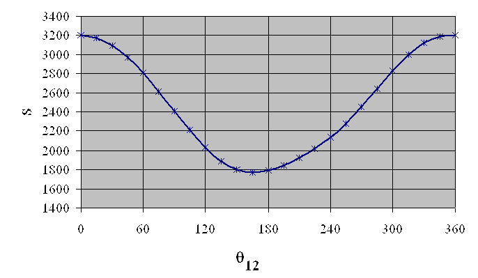
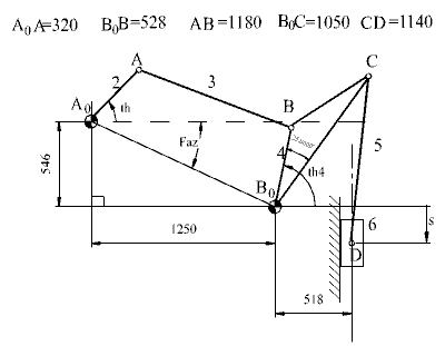 Fig a
Fig a
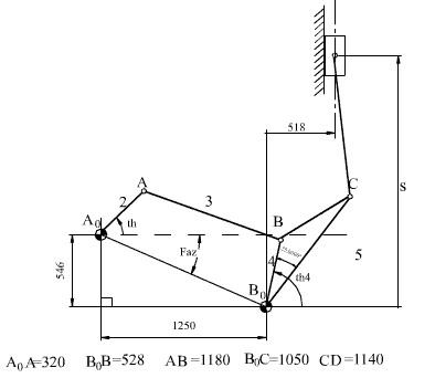 Fig b
Fig b
What if the slider-crank part of the mechanism is assembled differently as shown in Figures a and b? The Four-bar solution will not change. In Fig a since the input to the slider-crank mechanism must be along the slider axis, the input crank angle will be: q14 -a4+p/2 . To determine S,vertical displacement of the slider 6, into cell E16 type:
"=SliderCrank(Crank2 ;Coupler2 ;Eccentric ;1;(C15-Alfa4+PI()/2))"
and then copy this formula into cells E17-E40. For the mechanism shown in Figure b, in cell E16 the slider-crank formula for the determination of slider displacement will be in the form:
"= -SliderCrank(crank2 ;Coupler2 ;Eccentric ;-1;(C15-Alfa4+PI()/2)) "
Note that the slider displacement is considered positive when moving downwards in case (a) and upwards in case (b).
In the second case the configuration is -1, since the mechanism is assembled in the second form.
The slider displacement for the mechanism shown in (a) is as shown in (c) and that of (b) is shown in(d)
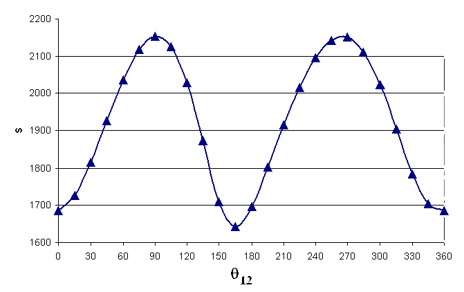
(In Figure d there is a double hump. why?).
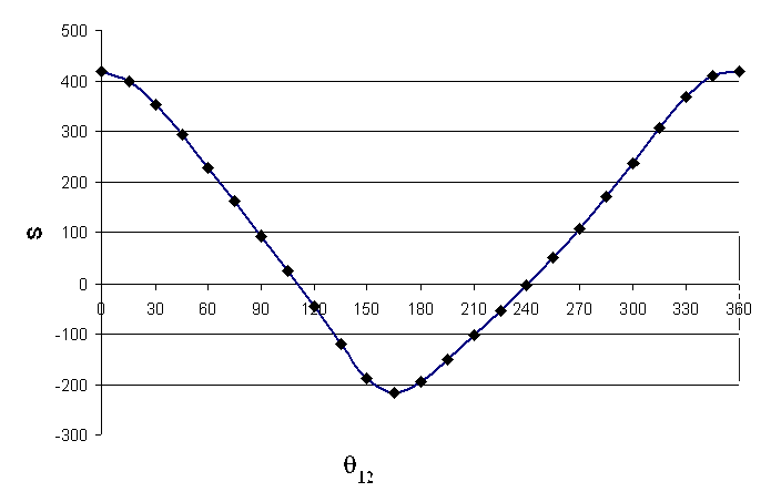 Fig. c
 Fig
d
Fig
d
Click here for the Excel File.
2.2. Basic trigonometry and simple mechanisms function files in MathCad
One can also write the basic function routines within mathematical packages such as MathCad or Matlab. When Mathcad is used these functions can be written as:

Note that for the inverted slider-crank mechanism, the file written in MathCAD is for a different model of inverted slider-crank mechanism than the one written in VBA for Excel. When all the functions are written on a MathCAD sheet and saved as a MathCAD file (say BasicMechanisms.mcd or BasicMechanisms.xmcd)(Download Basic Mechanisms2000.mcd or BasicMechanisms2000xmcd by clicking here). Whenever you want to use this file in another MathCAD sheet, from the Insert menu select reference and insert the name and the location of the file onto the new sheet. The result will be seen similar to the following line:

Of course, the place and the name of the file you have referenced must be different than the one seen above. Now on this MathCAD sheet you can use the functions that you have defined as if it is a standard MathCAD function.
Example
Consider the baler mechanism shown
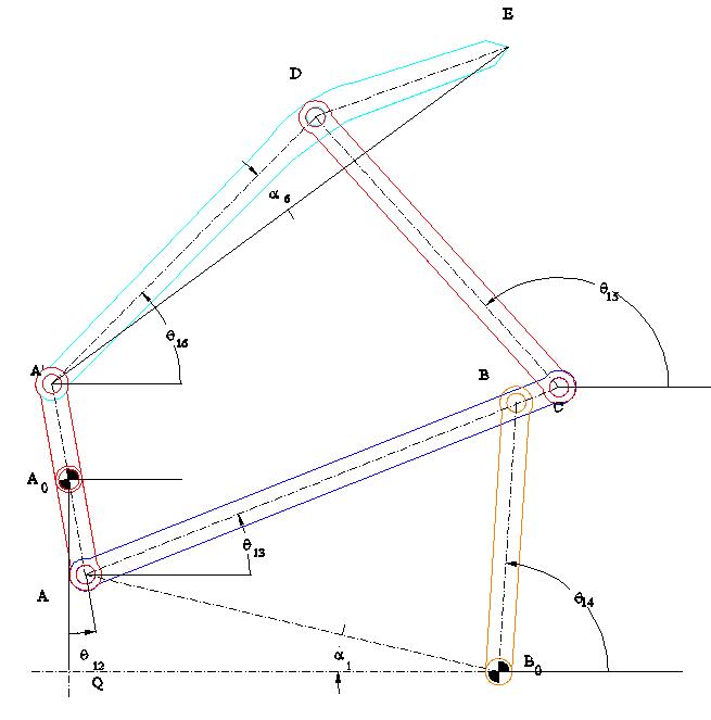
A0A=A0A'=a2; AB=a3; BB0=a4 ; BC=b3;A0Q=b1; QB0 =a1; CD=a5; AD= a6; DE=b6; <A'DE=g6
; Click for the solution in MathCadClick to download Baler.xmcd file
Click for the avi file created using MathCad
2.3. Basic trigonometry and simple mechanisms function files inMatLab
In case of Matlab® each of the above functions must be written as separate m-files with the name of the function as the file name. When you place these m-files into the MatLab workspace, you can use these functions in another m file. The above codes written in Mathcad and in Excel (in Basic language) are written as m-files in Matlab as:
function ac=angcos(u1,u2,opposite)
%apply cosine theorem to determine an angle when the three sides are known
u=(u1^2+u2^2-opposite^2)/(2*u1*u2);
ac=acos(u);
![]()
function mc=magcos(u1,u2,angle)
%apply cosine theorem to determine one side of the triangle when the two sides and the included angle is known
mc=sqrt(u1^2+u2^2-2*u1*u2*cos(angle));
![]()
function mag=mag(x,y)
%Determine the hypotenus of a right angled triangle when the other two sides (x,y) are given
mag=sqrt(x^2+y^2);
function fb=fourbar(crank,coupler,rocker,fixed,config,theta)
%Fourbar function to determine the rocker angle
sx=-fixed+crank*cos(theta);
sy=crank*sin(theta);
s=abs(sx+i*sy);
fi=angle(sx+i*sy);
si=angcos(rocker,s,coupler);
fb=fi-config*si;
![]()
function fbc=fourbarcoupler(crank,coupler,rocker,fixed,config,theta)
%Fourbar function to determine the coupler angle
sx=-fixed+crank*cos(theta);
sy=crank*sin(theta);
s=abs(sx+i*sy);
fi=angle(sx+i*sy);
si=angcos(rocker,s,coupler);
theta4=fi-config*si;
mu=angcos(coupler,rocker,s);
fbc=theta4-config*mu;
![]()
function fb2=fourbar2(crank,coupler,rocker,fixed,config,theta)
%Fourbar function to determine both the coupler and rocker angle. This function returns an array of two elements
fb2=zeros(1,2);
sx=-fixed+crank*cos(theta);
sy=crank*sin(theta);
s=abs(sx+i*sy);
fi=angle(sx+i*sy);
si=angcos(rocker,s,coupler);
mu=angcos(coupler,rocker,s);
fb2(2)=fi-config*si;
fb2(1)=fb2(2)-config*mu;
![]()
function sc=slidercrank(crank,coupler,eccentricity,config,theta)
%determines the slider displacenet of a slider crank mechanism for a given crank angle and link lengths
fi=asin((crank*sin(theta)-eccentricity)/coupler);
if config==1
fi=pi-fi;
end
sc=crank*cos(theta)-coupler*cos(fi);
![]()
function scc=slidercrankcoupler(crank,coupler,eccentricity,config,theta)
%determines the coupler angle of a slider crank mechanism for a given crank angle and link lengths
fi=asin((crank*sin(theta)-eccentricity)/coupler);
if config==1
fi=pi-fi;
end
scc=fi;
![]()
function sc2=slidercrank2(crank,coupler,eccentricity,config,theta)
%determines both the coupler angle and slider displacement of a slider crank mechanism for a given crank angle and link lengths
sc2=zeros(1,2);
fi=asin((crank*sin(theta)-eccentricity)/coupler);
if config==1
fi=pi-fi;
end
sc2(1)=fi;
sc2(2)=crank*cos(theta)-coupler*cos(fi);
![]()
function inv=invslider(crank,fixed,eccentricity,alpha,config,theta)
$determines the output link angle of an inverted slider crank mechanism for a given crank angle and link lengths
sx=-fixed+crank*cos(theta);
sy=crank*sin(theta);
s=abs(sx+i*sy);
fi=angle(sx+i*sy);
delta=s^2-eccentricity^2*sin(alpha)^2;
q=-eccentricity*cos(alpha)+sqrt(delta);
si=angle(eccentricity+q*cos(alpha)+i*q*sin(alpha));
inv=fi-config*si;
![]()
function inv2=invslider2(crank,fixed,eccentricity,alpha,config,theta)
%determines both the output angle and the relative displacement of the slide of an inverted slider crank mechanism for a given crank angle and link lengths
inv2=zeros(1,2);
sx=-fixed+crank*cos(theta);
sy=crank*sin(theta);
s=abs(sx+i*sy);
fi=angle(sx+i*sy);
delta=s^2-eccentricity^2*sin(alpha)^2;
q=-eccentricity*cos(alpha)+sqrt(delta);
si=angle(eccentricity+q*cos(alpha)+i*q*sin(alpha));
inv2(1)=q;
inv2(2)=fi-config*si;
![]()
Click here to obtain the above Basic M files (Basic M files.rar)
Example
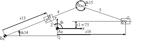
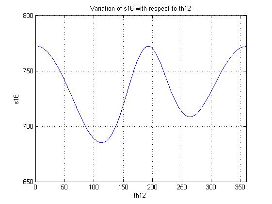
B0Q = a1 = 526, A0Q = b1 = 75, A0A = a2= 135, B0B = a4 = 826, BC = a5 = 481.
The m file written for this example is :
clc %Clear Command Window
clf %Clear figure windows
clear all %Clear all in the workspace
deg=180/pi; %To convert radians to degrees
a1=526; b1=75; c1=75; a2=135; a4=826; a5=481; %Link length definitions
for i=1:1:144
th12=5*i/deg;
th_12(i)=i;
alpha1=atan2(-b1,-a1);
d1=mag(a1,b1);
th14=invslider(a2,d1,0,0,1,th12-alpha1)+alpha1;
Bx=-a1+a4*cos(th14);
By=-b1+a4*sin(th14);
S=mag(Bx,By);
fi=atan2(By,Bx);
s16=slidercrank(S,a5,c1,1,fi);
A0x=0; A0y=0;
th_14(i)=mod(th14*deg,360);
s_16(i)=s16;
A0x=0; A0y=0; B0x=-a1; B0y=-b1;
Ax=a2*cos(th12); Ay=a2*sin(th12);
Cx=s16; Cy=c1;
x1=[A0x,Ax]; y1=[A0y,Ay]; %Joint locations of the links
x2=[B0x,Bx]; y2=[B0y,By]; x3=[Bx,Cx]; y3=[By,Cy];
t1=30; t2=50; %Thickness values for slider boxes
box11x=Ax+t1*cos(th14+pi/2)+t2*cos(th14); %Slider 3 box corners
box11y=Ay+t1*sin(th14+pi/2)+t2*sin(th14);
box12x=box11x-2*t2*cos(th14); box12y=box11y-2*t2*sin(th14);
box13x=box12x+2*t1*cos(th14-pi/2); box13y=box12y+2*t1*sin(th14-pi/2);
box14x=box13x+2*t2*cos(th14); box14y=box13y+2*t2*sin(th14);
x4=[box11x,box12x,box13x,box14x,box11x];
y4=[box11y,box12y,box13y,box14y,box11y];
box21x=Cx+t2; box21y=Cy+t1; %Slider 6 box corners
box22x=box21x-2*t2; box22y=box21y;
box23x=box22x; box23y=box22y-2*t1;
box24x=box23x+2*t2; box24y=box23y;
x5=[box21x,box22x,box23x,box24x,box21x];
y5=[box21y,box22y,box23y,box24y,box21y];
plot(x1,y1,'r-o',x2,y2,'g-o',x3,y3,'b-o',x4,y4,'m-',x5,y5,'c-','LineWidth',2.5)
axis equal
grid on
axis([-1.1*a1 2*a5 -3*b1 2*a2])
hold on
pause(0.01)
if(i<144)
clf
end
end
figure %Insert a new figure window
plot(th_12*5,s_16)
title('Variation of s16 with respect to th12')
xlabel('th12')
ylabel('s16')
grid on
xlim([0 360])
ylim([650 800])
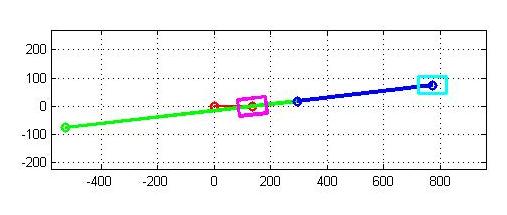
The result is the simulation of the mechjanism and the s16 versus crank angle plot as shown in Figure below.
Click to download the example.m file. Keep in mind that this m file will not run unless if you have placed the other m files used in the same place
As you can see, you can perform kinematic analysis using Excel, MathCad or MatLab. Basically the general approach is the same. You must first construct an algorithm with which you can compute the unknown parameters in sequence. In case of MathCad and Matlab you can use complex numbers (excel does not have this feature). However, Excel is the most available and cheapest product. Graphics is the simplest in Excel.