3.5 Graphical Solution of Loop Closure Equations
In performing the motion analysis the links are represented as straight lines that join the kinematic elements of the link. Since the tips of these lines are labelled, they are directed lines of certain magnitude and direction. Hence, in effect once we label the joints the diagram we thus obtain is the graphical representation of the loop closure equation (this was why we were able to write the loop closure equations, anyhow). For the graphical solution, this diagram must be drawn on paper by a certain scale, ks, which is generally called as the space scale. It is the ratio of the magnitudes drawn on the sheet to the original magnitude. If you are to draw the mechanism on the computer, you may use the exact dimensions, no matter how big or how small the mechanism is in its actual size.
 |
 |
|
Figure (b). |
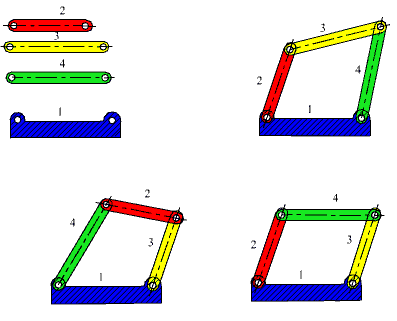
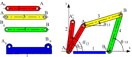
Consider the four-bar mechanism in F(a). If four links of different dimensions were given, you would have several different possible ways of joining these links. However, if we know an assembled position, the mechanism and its motion must be unique. Let us determine the positions of the links when the input link is rotated to some other angular position q12'.
The new position of the vector A0A (A0A') is completely known when is q12' given. The vector loop equation:
A0A+AB = A0B0+B0B
must also be true when A is replaced by A' (known point) and B is replaced by B' (unknown), since the mechanism will form a closed loop in this second position:
A0A'+AB' = A0B0+B0B'
This equation can also be written in the form:
A'B' = A0B0-A0A'+B0B'
or:
A'B' = A'A0+A0B0+B0B'
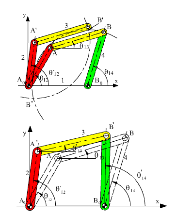
Figure (c).
The sum of the vectors A'A0+A0B0 is the vector A'B0. We know the magnitude and direction of the vectorsA'A0 and A0B0. We know the magnitudes of the vectors A'B' and B0B'. Since the starting positions A' and B0 for the vectors A'B' and B0B'are known, in order to determine the new position of B (B'), one need only construct circles with centres at A' and B0 and radii equal to the corresponding link lengths (AB and B0B, respectively) as shown in Figure 2.21b. The two circles will have two intersections B' and B";. However, one of these solutions is discarded since the mechanism cannot jump into one of these positions without disconnecting the joints (Fig. 2.21c). If the two circles drawn cannot intersect at all, then the mechanism cannot be assembled for that crank angle q12'.
The above procedure is nothing but the solution of a triangle whose three sides are known. For great many mechanisms the position analysis using graphical technique will reduce to the solution of a triangle. As is well known, a triangle is fully determined if we know the three sides (SSS), two angles and one side (ASA) or the two sides and one angle (SAS or SSA). All these three cases can be encountered in the position analysis.
Example 2.1.
Consider an inverted slider-crank mechanism shown in Figure 2.22a. We are asked to determine the positions of the links when the input link, 2, is rotated to some other angular position q12'. The loop closure equation is:
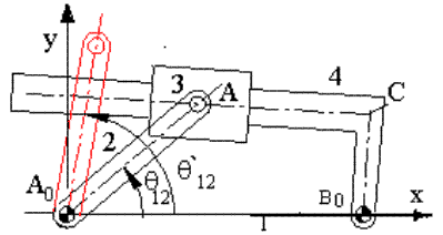
A0A=A0B0+B0C+CA
The vector A0B0 is fixed. The vector A0A has a fixed magnitude and its angular orientation is defined by the given angle q12 . B0C has a fixed magnitude but an unknown angular orientation whereas for the vector CA both the magnitude and the direction can change. However, the vectors B0C and CA are perpendicular to each other and the axis of the slider must always pass through point A. Points AB0C will always form a right angled triangle. In order to construct the triangle AB0C for the given points A and B0 (defined by the vectors A0A and A0B0), we draw a circle with centre at B0 and radius B0C. If we now draw a line passing through A and tangent to this circle, the new positions for links 3 and 4 will be found.
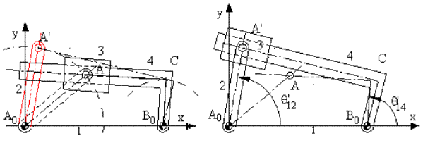
In a complete motion analysis it is necessary to draw the mechanism in various phases of its cycle (for all possible input positions). Through such an analysis one can determine the limiting positions (positions at which there is the displacement of the link involved is at an extreme position, e.g. at this position there is a reversal of motion)
Example 2.2.
Consider the slider crank mechanism shown in the figure below. The input variable is the angular position of link 2 (crank) with respect to the fixed link. The vector loop equation is:
A0A+AB=A0Q+QB
In order to separate the variable distance s14 and the fixed distance A0Q (eccentricity) the vector A0B is separated into its components. In this vector equation, the direction of the vector AB and the magnitude of the vector QB are the unknowns. One can solve this vector equation for any crank angle by first locating point A for that crank angle and then drawing an arc of centre A and radius equal to the length AB. The intersection of this arc with the slider axis is the new location of point B.
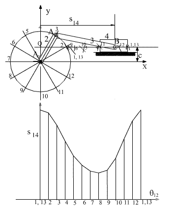
For a systematic solution corresponding to different input angles, first the locus of A is drawn (which is a circle with centre A0 and radius A0A). Corresponding to different input crank angle this circle is divided into a number of increments. For a detailed analysis the number of increments must be large. However in the above figure the circle is divided into 12 parts corresponding to 300 increments. The location of point A for every value of the input variable is denoted by Ai (i=1 to 12). By drawing circular arcs with centre Ai and of radius AB, we determine the intersection of this arc with the slider axis Bi. Next, the horizontal distance of the slider with respect to the origin can be plotted as shown.
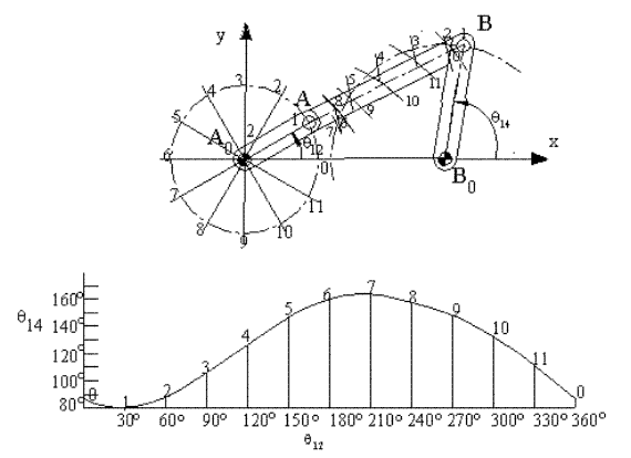
The diagram that gives the angular or linear displacement of a link with respect to the input parameter is usually called as the displacement diagram. If the time rate of change of the input parameter is a constant this diagram is also the time-displacement plot. For a four-bar mechanism, the angular displacement of link 4 with respect to link 2 is given in the figure below. In some other problems we may be interested in the curve described by one of the points on a floating link (a link which is not connected to the fixed link). These curves are generally known as coupler curves. the coupler curve of a four-bar mechanism that traces an approximate straight line for a certain portion of crank rotation is shown. Note that one can perform the graphical analysis either by using the drawing equipment such as a campus and a ruler, or use any drawing program such as AutoCAD ®, CadKey ® or the like. If each of these positions are stored in a separate file, the mechanism can be very easily animated on the screen. CAD programs such as Catia ®, ProE ® , Ideas ® or Solidworks ®, etc. can simulate the motion, provided the joints are correctly defined.
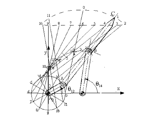
(A0A=1, A0B0=2, AB=B0B=BC=2.5)
When the mechanism has several loops, the vector loop equations can be solved graphically in sequence. The mechanism shown below is used to move a mixer vertically up and down. A0A is the driving link (there is a lever attached).
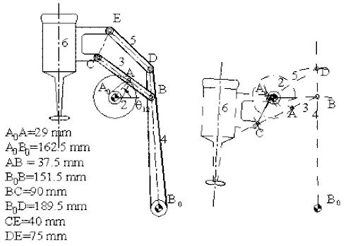
The first loop is the four-bar mechanism A0ABB0 (links 1,2,3 and 4). The vector loop equation is:
A0A+AB= A0B0+B0B
This vector loop equation can be solved for a new position of the input crank (link 2), as described for the four-bar and the new location of point B can be found. Since point C is on link 3 and D is on link 4, the positions of these points can also be found by noting that we know the position of two points on these links and the distances are fixed (on link 3, we know points B and A. point C is on the line BA and at a distance 90 mm from point B. Similarly, point D on link 3 is on the line B0B and at a distance 189.5 mm from point B0).
Next, consider the loop BCEDB (links 3,6,5 and 4). The vector loop equation is:
BC+CE=BD+DE
In this vector loop equation the vector BC and BD are known (both in magnitude and direction) and the magnitudes of the vectors CE and DE are given. We again have a triangle (CED) whose three sides are known. Hence the intersection of the circular arcs of radii CE and DE from points C and D respectively, will give us the position of point E.
For the analysis of complex mechanisms, such as those shown in figure below, one must use the trial-and-error method for the solution of the loop closure equations. These equations are:
PA0+A0A=PB0+B0B+BA
PQ+QC=PB0+B0B+BC
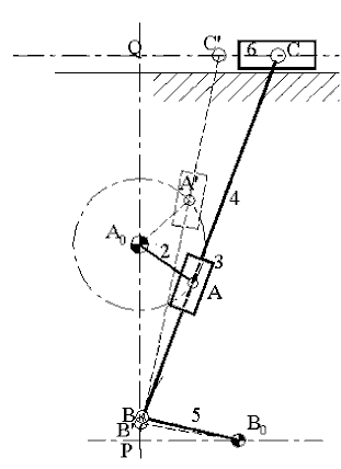
In both of these equations there are three unknowns; therefore these equations must be solved simultaneously. There are four unknowns in the two equations (the direction of B0B, magnitude of QC, magnitude and direction of BA). Since the direction of BC is that of BA, it is not an additional unknown. The path of point B is a circle and the path of point C is a straight line relative to the fixed link. Also point A, whose position is defined by the input variable must be on the line BC. By trial and error we move the straight line BC such that the following conditions are all satisfied:
