3.6 Step-Wise Solution of the Loop Closure Equation
As shown in the previous section, for simple mechanisms the solution of the loop closure equations reduces to the solution of a triangular relation. The triangular relations can as well be solved analytically. In this approach, rather than obtaining an explicit function between the input variable and other position variables, our aim will be to obtain a set of equations which, when solved in steps, will yield the value of all the unknown variables. Such a solution is a closed form solution and, furthermore, it is very suitable for a numerical solution using a computer, programmable calculator, or even on a simple calculator.
As a first example, consider a problem in which we want to determine the position of all the links of an off-set slider-crank mechanism shown below for different crank angles q12. The link lengths denoted by a1, a2, a3 are known.
The vector loop equation is:
A0A= A0B +BA
In rectangular form, these vectors can be written as:
A0A= a2(cosq12 i + sinq12 j)
A0B= xi + a1j
BA= a3(cosq13 i + sinq13 j)
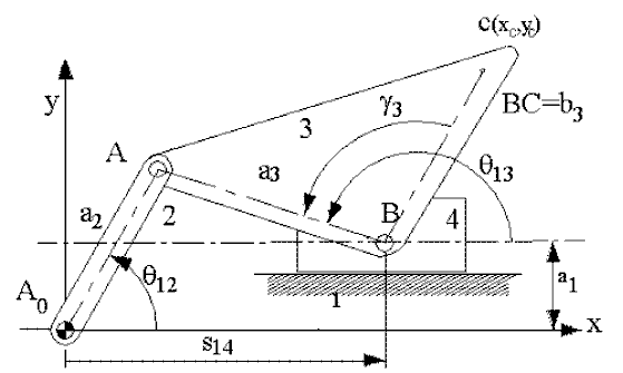
Figure 2.28.
Equating x and y components separately, the loop closure equation will yield two scalar equations:
a2cosq12 = s14 + a3cos q13 (1)
a2sin q12 = a1 + a3sinq13 (2)
Rewriting these equations:
![]() (3)
(3)
![]() (4)
(4)
For a given value of the input variable, q12, one can solve for q13 from (3) and substitute the values of q13 and q12 into equation (4) to obtain the corresponding value of s14. The variable s14 can be solved only after q13 is solved from (c). If we are to determine the co-ordinates of a point C (xc, yc), we can write:
xc = s14 + b3cos(q13 -g3) (5)
yc = a1 + b3sin(q13 -g3) (6)
Again equations (5) and (6) can be solved only after equations (3) and (4) are solved.
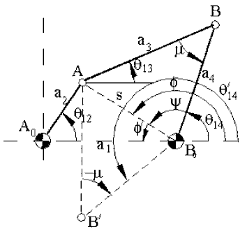
Since the scalar equations obtained from the loop closure equations are non-linear, the method of solution will differ from one mechanism to the other. The method used for the analysis of a four-bar is known as the Raven's Method. In the four-bar mechanism shown above, the link lengths (a1, a2, a3, a4) are given. We would like to determine the position of all the links for a given value of the input variable, q12.
Similar to the method used in geometrical analysis, first consider the triangle A0AB0. Since the two sides (a1, a2) and the included angle (q12) are known, for this triangle the length of the third side (AB0 = s) and angle f of the triangle can be determined. Note that the length, s, and angle f are variable. Using the cosine theorem:
![]() (1)
(1)
![]() (f=p- f’) (2)
(f=p- f’) (2)
Another form of calculating s and f’, especially when a calculator has polar-to-rectangular conversion key, is to equate the x and y components:
s cosf = a2cosq12-a1 = Horizontal component of B0A = xs (1’)
s sinf = a2sinq12 = Vertical component of B0A = ys (2’)
Now, if the values on the right-hand side of these equations are determined and if a rectangular-to-polar conversion is made, one will obtain s and f as the output directly. This will give the correct quadrant for the angle f at every instant. In computers a similar result can be obtained by using inverse tangent function with double argument (ATAN2 (xs, ys)) to obtain the correct quadrant for f.
Referring to the triangle ABB0 and applying cosine theorem:
![]() (3)
(3)
![]() (4)
(4)
The magnitudes of f’ and y are both less than 1800and y is always positive. If equations (1) and (2) are used, than the sign of f’ must be checked (if you use rectangular-to-polar conversion the calculator gives the correct quadrant). The sign of sinf’ must be of the same sign as sinq12. The plus or minus sign for m refers to two different solutions of a four-bar mechanism as shown in the figure. The angle m is known as the "transmission angle" whose importance is explained in Chapter 4.
The unknown position variables q13 and q14 can be easily determined as:
q14= f-y (5)
q13 = q14-m (6)
Hence, we have obtained a set of equations which must be solved in steps.
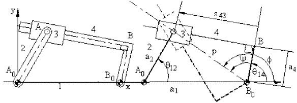
pcosf =a2cosq12 -a1 (1)
psinf =a2sinq12 (2)
(when solving with a calculator, use P - R conversion to determine p and f)

The derivation of these equations is left as an exercise (As a hint, the solution of the two triangles A0AB and AB0B in steps results with the above equations).
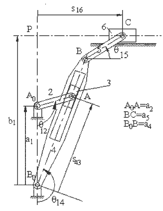
In great many mechanisms, the stepwise solution will require the solution of four-bar, slider-crank or inverted slider-crank loops in steps. For example, the quick-return mechanism shown below links 1,2,3 and 4 form an in-line inverted slider-crank mechanism while links 1,4,5 and 6 form a slider-crank mechanism. For a given value of the input variable, q12, the angle q14 and s can be determined. In case of the slider-crank mechanism, with q14 as the input variable, the position variables q15 and s6 are found. In such an analysis, one must be concerned with the reference axes and how the variables are to be measured with respect to the reference axes.
 |
|
The first two equations are the solution of the triangle A0AB0. The last two equations are the solution of the slider crank mechanism formed by links 1,4,5 and 6.
Example
Consider the six link mechanism shown which is used as a garage door. We are to determine the position of the links when the input crank angle q12 is given. Let:
A0B0 =a1; A0A=a2; A0D=b2; AB=a3; BC=b5; BB0=a4; CD=a6
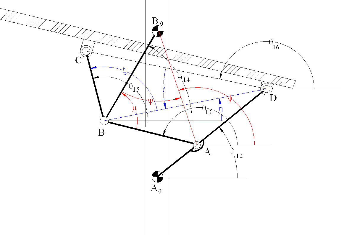
Noting that the links 1,2,3,4 (A0ABB0) form a four-bar mechanism, referring to the equations derived for the four-bar:
s cosf = -a2cosq12 = Horizontal component of AB0= xs
s cosf = -a2cos q12+a1 = Vertical component of AB0 =ys
|B0A| = s = ![]() ; f = atan-1(xs;ys)
; f = atan-1(xs;ys)
![]()
![]()
q14 = f-y
q13 = q14-m +p
(y, f and m are as defined for the four bar mechanism in Figure ). The coordinates of points B and D relative to an x,y frame with center A0are :
xD=b2cosq12
yD=b2sinq12
xB=-a4cosq14
yB=a1-a4sinq14
The distance BD and the angle it makes with the horizontal is:

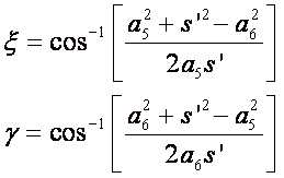
From the triangle BDC:
or
and
q15=h+x
q16=h+p-g
Hence all the unknown position variables are determined in steps.These equations are valid for every position of q12.Note that these equations can be solved in steps (one after another). If the independent variable was selected as the angle of the door q16, then these equations must be solved simultaneously.